Eddy current testing probe and eddy current testing method

a technology of eddy current testing and testing probe, which is applied in the direction of magnetic property measurement, material magnetic variables, instruments, etc., can solve the problem that the probe cannot be used in very narrow places, and achieve the effect of enhancing the resolution of a flaw detection result and small thickness

Active Publication Date: 2015-04-23
MITSUBISHI HEAVY IND LTD
View PDF8 Cites 10 Cited by
  • Summary
  • Abstract
  • Description
  • Claims
  • Application Information

AI Technical Summary

Benefits of technology

[0011]Since the exciter coils and the detector coils are arranged on a single surface, typically on a single plane, the eddy current testing probe of the present invention has a small thickness, and allows for performing eddy current testing even in narrow spaces.
[0030]According to the present invention, since exciter coils and detector coils are arranged on a single surface, the eddy current testing probe has a small thickness, and allows for performing eddy current testing even in narrow spaces.

Problems solved by technology

Therefore, the eddy current testing probe of Japanese Patent No. 3343860 has a thickness of those of the detector coils and the exciter coil, and the probe may not be used in very narrow places.

Method used


Image

  • Eddy current testing probe and eddy current testing method
  • Eddy current testing probe and eddy current testing method
  • Eddy current testing probe and eddy current testing method

Examples


first embodiment

[0042]The embodiments of the present invention will be described below with reference to the accompanying drawings.

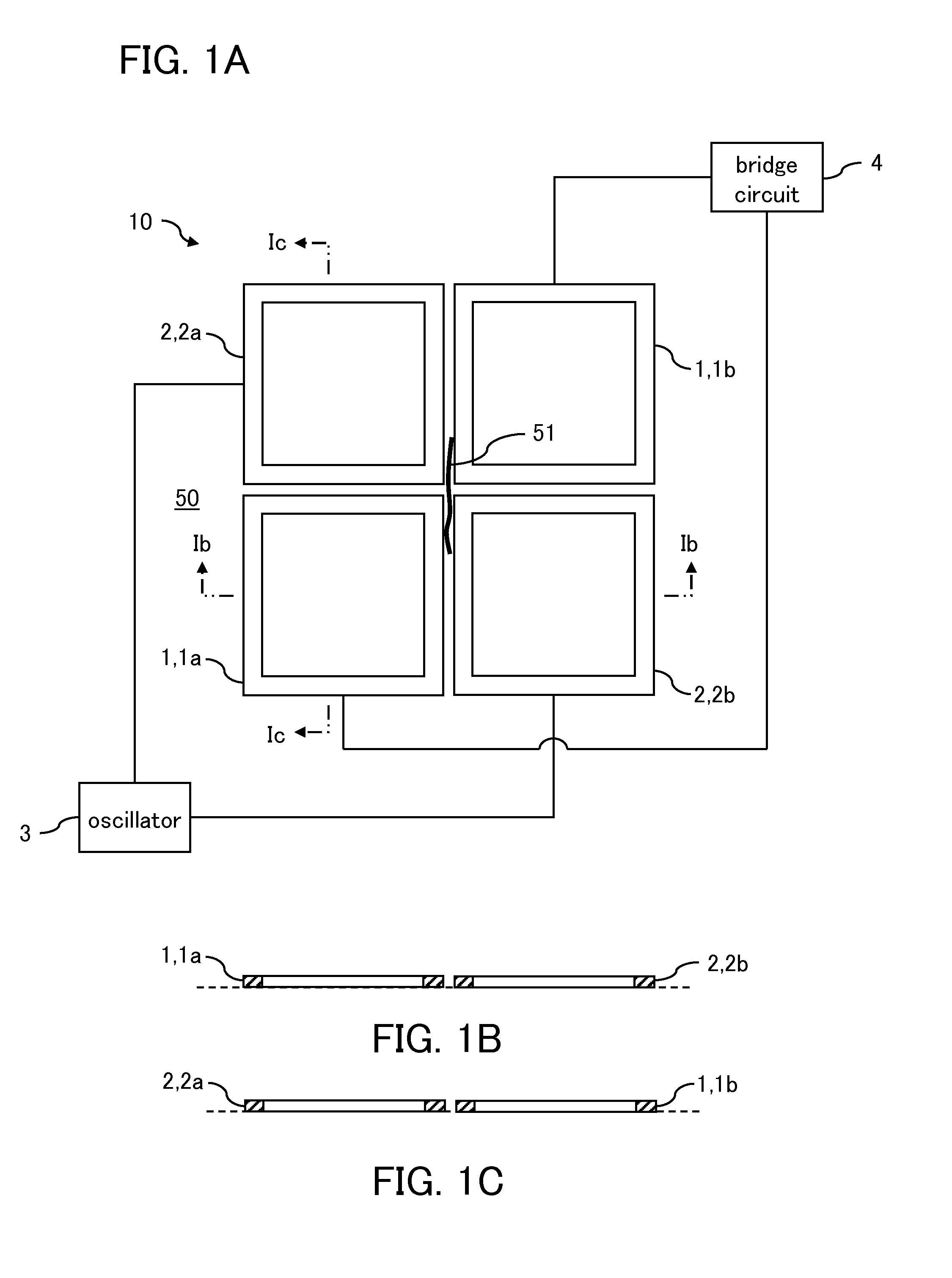
[0043]An eddy current testing probe 10 of the present embodiment is used for detecting a flaw 51 present on a surface of a test object 50 that is positioned thereunder, while moving over the test object 50.

[0044]The configuration of the eddy current testing probe 10 will be described below.

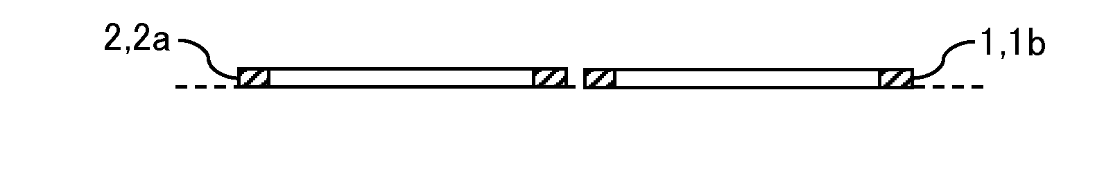
[0045]The eddy current testing probe 10 includes, as shown in FIG. 1, detector coils 1, and exciter coils 2 for generating alternating magnetic fields to generate eddy currents EC near a surface of the test object 50.

[0046]The detector coils 1 include a pair of a first detector coil 1a and a second detector coil 1b. The first detector coil 1a and the second detector coil 1b are differentially connected to each other. For each detector coil 1, a wound coil is used that has a wire wound therearound and is formed in a rectangle shape, and the first detector coil 1a and the second detecto...

second embodiment

[0068]An eddy current testing probe 20 according to a second embodiment relates to a multi coil type eddy current testing probe.

[0069]The eddy current testing probe 20 includes, as shown in FIG. 5, a total of 12 coils C arranged in a matrix pattern on a single plane, i.e., six coils C in a row direction X and two coils C in a column direction Y. Each coil C is made of, like the detector coils 1 and the exciter coils 2 in the first embodiment, a wound coil having a wire wound therearound. However, it is assumed that, in the second embodiment, all of the 12 coils C have an identical electromagnetic property. These coils C are denoted as C11, C12, C13, C14, C15, C16, C21, C22, C23, C24, C25, and C26, as shown in FIG. 5. However, they are collectively denoted as coils C when they do not need to be distinguished from one another.

[0070]Note that, the number of the coils C (i.e., 12) is only an example, and any number of the coils C can be provided in the row direction X and in the column ...

third embodiment

[0086]Next, a third embodiment relates to an eddy current testing probe 30 that performs flaw detection in which a shallow flaw can be detected.

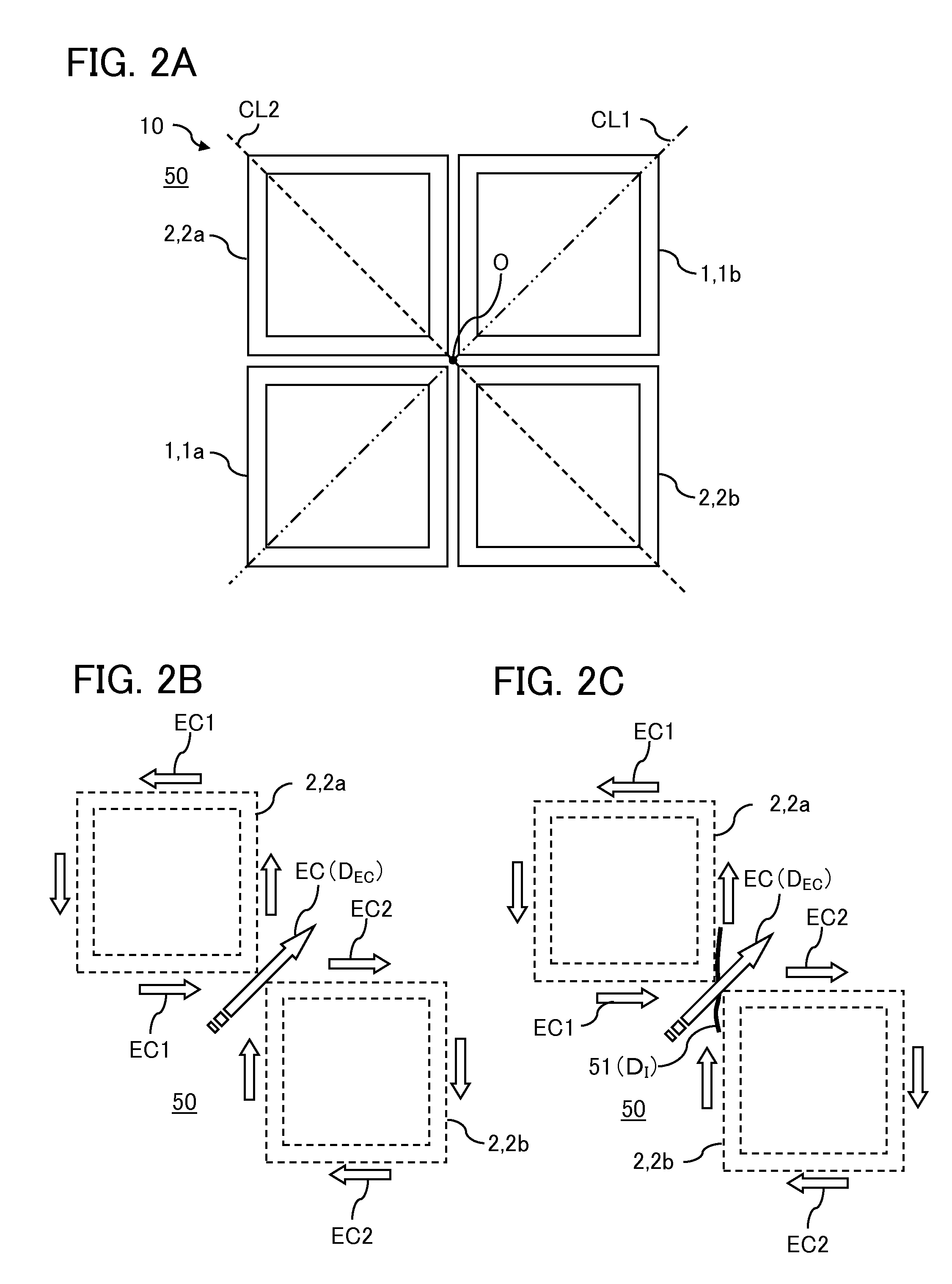
[0087]The present inventors have found that, with the eddy current testing probe 10 according to the first embodiment, the capability of detecting the flaw 51 passing a position of FIG. 1 may be lowered when the flaw 51 is present in a shallow position. Note that the position of FIG. 1 means a boundary portion between the first detector coil 1a and the second exciter coil 2b, and a boundary portion between the first exciter coil 2a and the second detector coil 1b, in the eddy current testing probe 10.

[0088]Thus, the present inventors have conducted studies and found that the eddy current testing probe 30 in which, as shown in FIG. 9, the pair of the first detector coil la and the second exciter coil 2b, and the pair of the first exciter coil 2a and the second detector coil 1b are arranged offset from each other, can detect the flaw 51, which...


PUM

PropertyMeasurementUnit
eddy current testingaaaaaaaaaa
magnetic fieldaaaaaaaaaa
symmetryaaaaaaaaaa

Abstract

An eddy current testing probe includes: exciter coils 2 including a first exciter coil 2a and a second exciter coil 2b identical with each other and arranged in point symmetry, and each of which generates an alternating magnetic field to generate an eddy current in a test object; and detector coils 1 including a first detector coil 1a and a second detector coil 1b identical with each other, arranged in point symmetry, arranged in phase, and differentially connected to each other. The exciter coils 2 and the detector coils 1 are arranged on a single plane. A center of symmetry O on a center line of symmetry CL2 of the coils 2a, 2b, is identical with a center of symmetry O on a center line of symmetry CL1 of the coils 1a, 1b, and the CL1 intersects with the CL2 at a right angle.

Description

BACKGROUND OF THE INVENTION[0001]1. Field of the Invention[0002]The present invention relates to a probe used for eddy current testing used for non-destructive testing.[0003]2. Description of the Related Art[0004]As a non-destructive testing method for metals, an Eddy Current Testing (ECT) is known. In this flaw detection method, an eddy current is generated on a surface of a test object by an exciter coil, and changes in a voltage (or changes in an impedance) of a detector coil caused by the influence of this eddy current are observed to detect a flaw developed in the test object.[0005]The present inventors have proposed an eddy current testing probe that can accurately detect a flaw, in Japanese Patent No. 3343860. The eddy current testing probe of Japanese Patent No. 3343860 has an advantage of accurately detecting a flaw on a specimen based on a voltage difference generated between detector coils resulting from magnetic fluxes, even if a diagonal lift-off change occurs, which is...

Claims


Application Information

Patent Timeline
Patent Type & Authority Applications(United States)
IPC IPC(8): G01N27/90
CPCG01N27/9033G01N27/904G01N27/9013
Inventor KUROKAWA, MASAAKISHICHIDA, TOMONORI
Owner MITSUBISHI HEAVY IND LTD
Why Eureka
Try Eureka