

Alternating sagd injections
- Summary
- Abstract
- Description
- Claims
- Application Information
AI Technical Summary
Benefits of technology
Problems solved by technology
Method used
Image

Examples
experiment 1
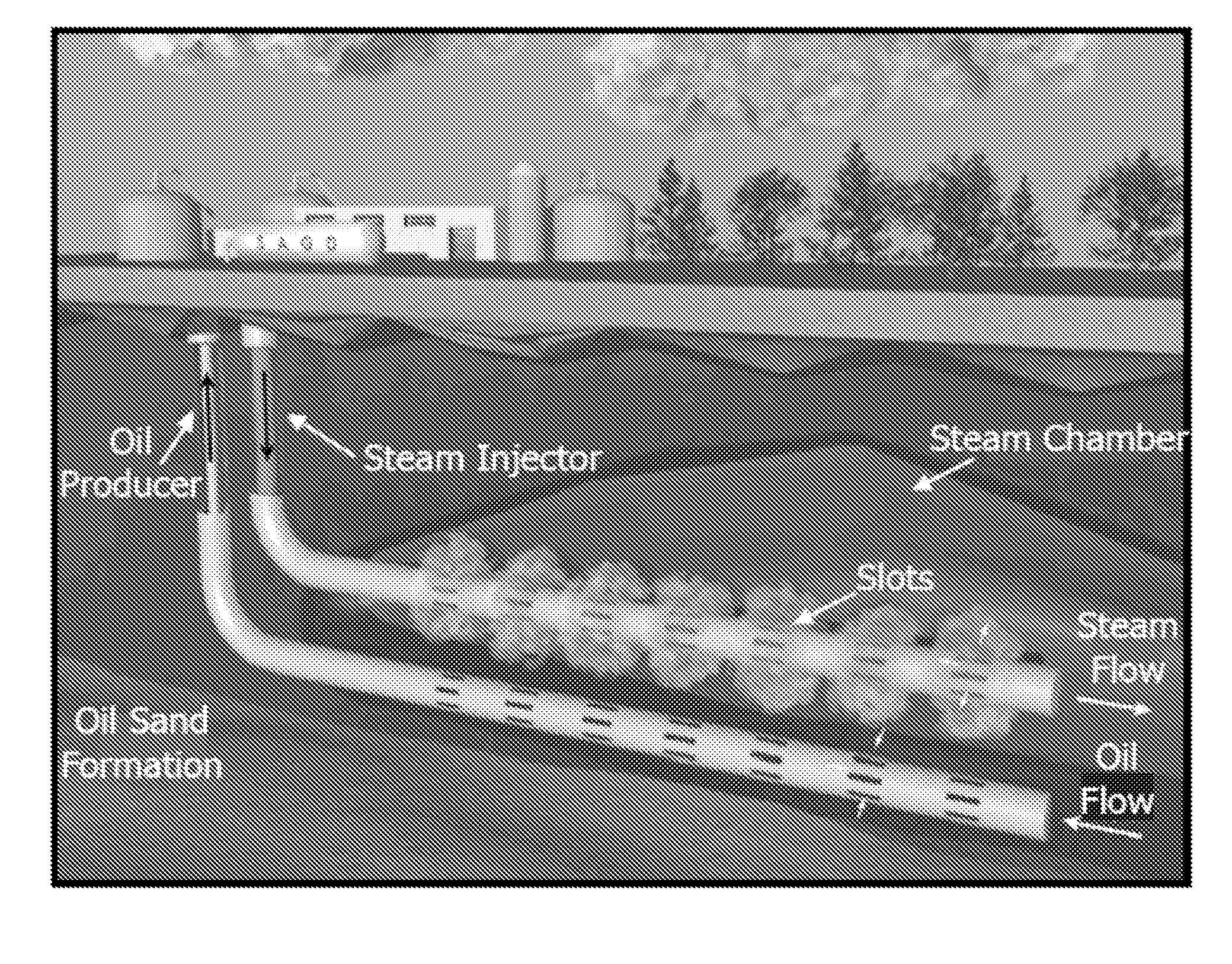
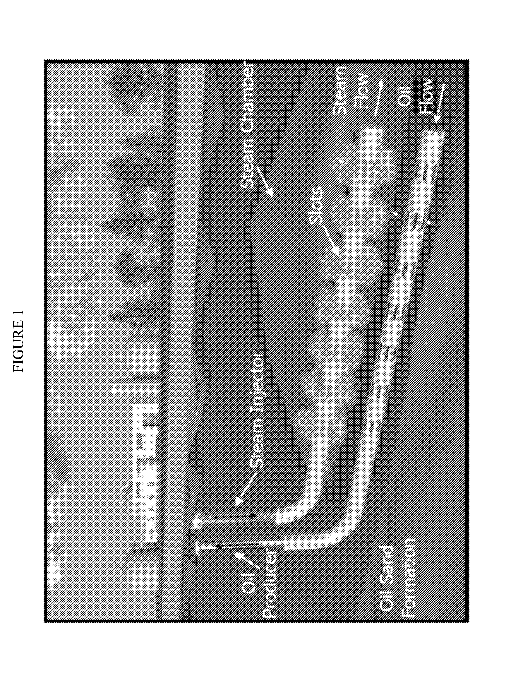
[0078]A traditional DSG-SAGD with alternating injections of steam and steam mixed with CO2 was simulated using a numerical simulator such as CMG-STARS to evaluate the potential benefits of the alternating injections. The simulation was modeled after an Athabasca oil sands reservoir of 100 meters in width by 30 meters in height by 850 meters in length. Two (850 m long) horizontal wells were placed near the bottom (producer) and in the middle (injector) of the reservoir, separated by 5 m in the vertical direction. The lower horizontal well was placed 1 m above the bottom of the oil bearing sands. Initially, a pre-heating period of 90 days was used to heat the region between the wells by circulating steam and CO2 in both the injection and production wells (similar to field pre-heating for SAGD).
[0079]The temperature of the steam injection was 250° C. and the temperature of the steam and 10 wt % CO2 mixture was 245° C. and injected at 40 bars. The fuel and oxygen were 10° C. when delive...
experiment 2
[0084]A DSG-SAGD with alternating injections was compared with traditional SAGD and DSG-SAGD using continuous co-injection of steam and CO2. The SAGD and DSG-SAGD simulations used the same configuration and parameters as the simulation in Experiment 1.
[0085]FIG. 7 shows the comparison of the oil production rates expected for these three processes. Initially, the traditional SAGD produces higher amounts of oil, but then begins to level off. It should be noted that a much greater water and energy consumption is necessary for SAGD. Thus, the improved oil production rates are offset by the high cost of the traditional SAGD process.
[0086]Comparing the two DSG-SAGD processes, the alternating injection (dashed line) has a higher oil production rate than the continuous co-injection process. The difference can be attributed to the increased CO2 dissolution in the bitumen during the steam-only phase of injection in the alternating injection process. More CO2 dissolution means less CO2 accumul...
PUM
 Abstract
Description
Claims
Application Information