Fluid Flow Regulating Device Having High Resistance To Corrosion

Inactive Publication Date: 2015-04-30
EMER SPA
View PDF30 Cites 1 Cited by
  • Summary
  • Abstract
  • Description
  • Claims
  • Application Information

AI Technical Summary

Benefits of technology

The device prevents direct contact between the body and the components, reducing corrosion and damage caused by electric arcs. It uses a spacer element made of a material with an intermediate electric potential to create less intense arcs. This results in a less aggressive corrosion process.

Problems solved by technology

This reduces weight has positive repercussions on vehicle performance.
One problem that has been encountered however is due to the fact that aluminum has a low electric potential.
Consequently, if the aluminum associates with a metal material having a medium / high electric potential (such as, for example, the stainless steel often used for various valve components) it acts as an anode and is thus subject to galvanic corrosion phenomena.
Current valves with aluminum valve bodies and stainless steel components do not satisfy current corrosion resistance tests.
During these tests the corrosion reaches the sealed zone between the valve body and fittings which leads to gas leaks.
However, it is difficult to control the application process and the layer can be partially removed during movement of the component and / or during the final assembly of the gas system.

Method used


Image

  • Fluid Flow Regulating Device Having High Resistance To Corrosion
  • Fluid Flow Regulating Device Having High Resistance To Corrosion
  • Fluid Flow Regulating Device Having High Resistance To Corrosion

Examples


Embodiment Construction

)

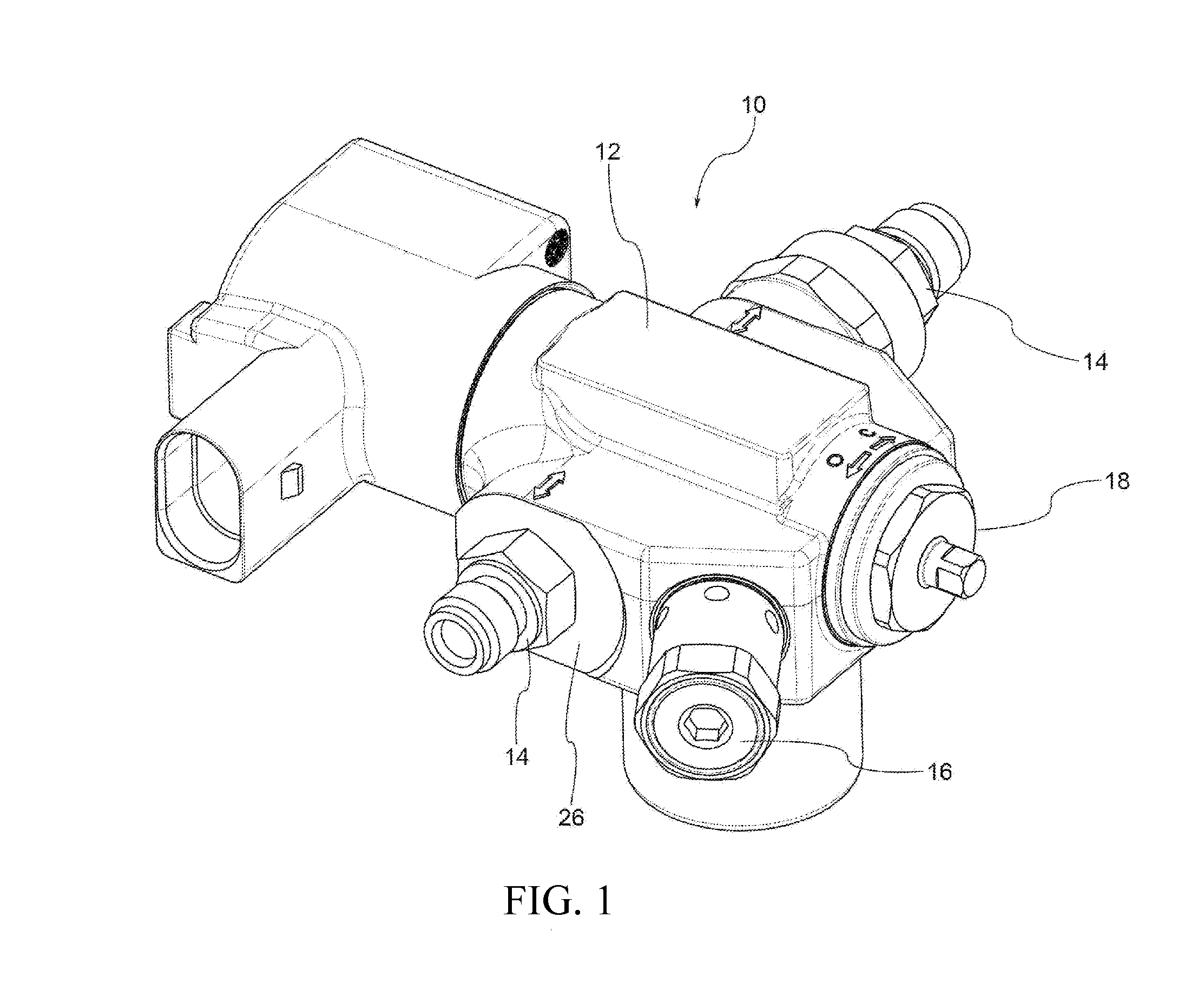
[0017]FIG. 1 shows multifunction valve 10 according to the prior art. Multifunction valve 10 includes valve body 12, one or more fittings 14 (in this case two fittings) assembled to valve body 12 to each permit the attachment of a respective pipe (not shown) to valve body 12, as well as a series of parts or devices of various types indicated by reference numerals 16 and 18.

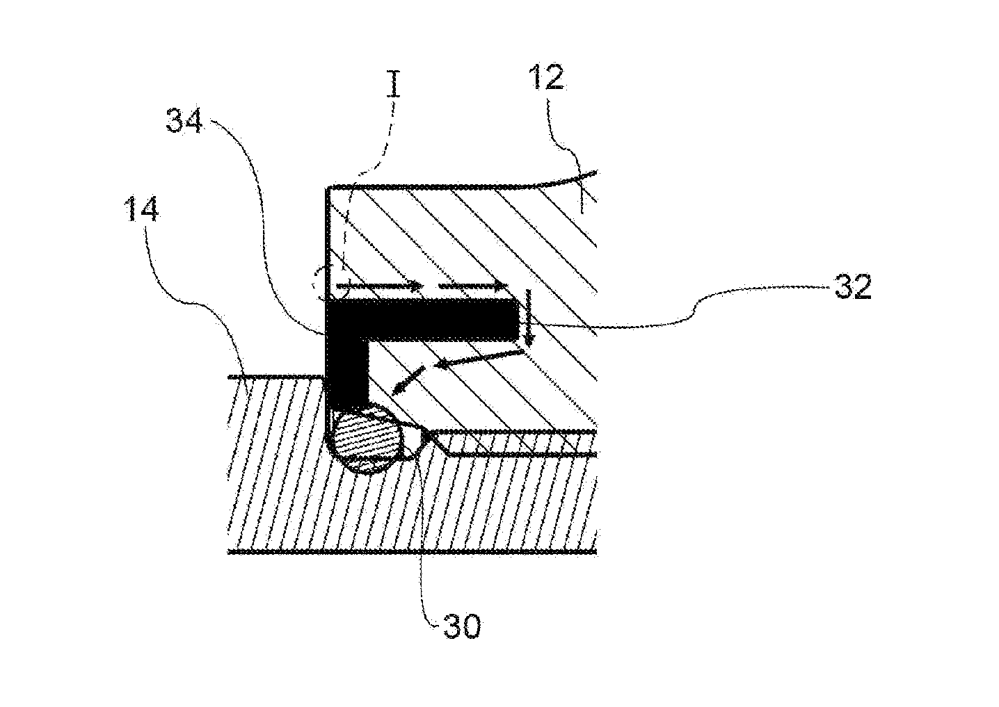
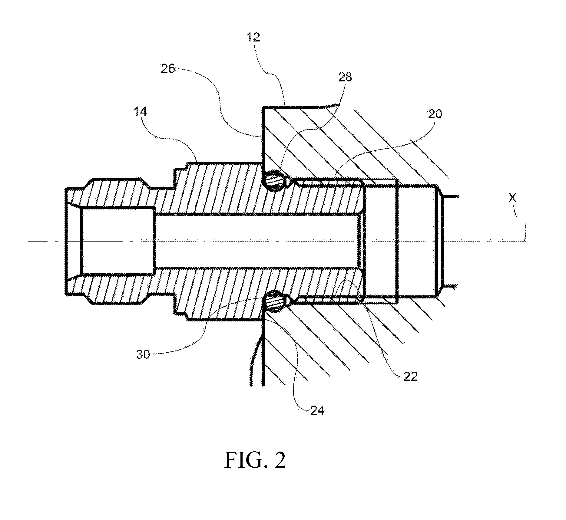
[0018]FIG. 2 shows the coupling between one of the two fittings 14 with valve body 12. Fitting 14 includes threaded cylindrical coupling portion 20 which is screwed into corresponding threaded cylindrical seat 22 provided in valve body 12. Fitting 14 further presents abutment surface 24 lying in a plane perpendicular to the axis (indicated as x) of coupling portion 20, which in the assembled condition of valve 10 abuts against flat surface 26 of valve body 12 extending around seat 22. O-ring 28 is mounted on fitting 14 between coupling portion 20 and abutment surface 24 and, in the assembled condition of valve 10...


PUM


Abstract

A device has a body made of a first material, for example aluminum, and a component coupled to the body and made of a second material different from the first. The device further includes, between the body and the component, a spacer element of annular shape arranged around the component so as to be in contact on the one hand against the body and on the other against an abutment surface of such component, preventing, or at least reducing, direct contact between the component and the body. In some embodiments, the spacer element is made of a third material having an electric potential value between the first two materials.

Description

CROSS-REFERENCE TO RELATED APPLICATIONS[0001]This application is a continuation of International Application No. PCT / IB2013 / 055201 having a filing date of Jun. 25, 2013, entitled “Fluid Flow Regulating Device, Particularly for Automotive Gas Systems, Having High Resistance to Corrosion”, which claimed priority benefits from Italian patent application No. BS2012A000097 filed on Jun. 28, 2012. The present application also claims priority benefits from the '097 Italian application. The PCT / IB2013 / 055201 international application is hereby incorporated by reference herein in its entirety.FIELD OF THE INVENTION[0002]A fluid flow regulating device, in particular for automotive gas systems, has a body made of a first material and a component coupled to the body made of a second material different from the first. More specifically, a multi-function valve for automotive gas systems, having a valve body in aluminum to which one or more stainless steel fittings are attached for connecting one ...

Claims


Application Information

Patent Timeline
IPC IPC(8): F02M21/02F16L25/02F16K27/00
CPCF02M21/0296F16L25/021F16K27/00Y02T10/30
Inventor BRIZZOLARI, GIULIODEFILIPPI, ROBERTO
Owner EMER SPA
Why Eureka
Try Eureka