Method of controlling an inkjet printhead, an inkjet printhead suitable for use of said method, and an inkjet printer comprising said printhead

a technology of inkjet printing and inkjet printer, which is applied in the direction of printing, other printing apparatus, etc., can solve the problems of reducing the print characteristic, slow change of material properties and particularly expansion characteristics of electromechanical transducers, and affecting the operation of the electromechanical transducer

Inactive Publication Date: 2008-04-15
OCE TECH
View PDF8 Cites 2 Cited by
  • Summary
  • Abstract
  • Description
  • Claims
  • Application Information

AI Technical Summary

Benefits of technology

[0011]The object of the present invention is to obviate the above disadvantages. To this end, a method has been developed which includes the steps of measuring the electric impedance of the electromechanical transducer, and adapting the actuation pulse on the basis of the measured impedance. In the method according to the present invention, the impedance, i.e. the current / voltage characteristic, of the electromechanical transducer is measured in order to adapt the actuation pulse itself. In other words, the impedance of the transducer is measured during the application of the pulse, so that the effect of this pulse can be determined simultaneously with its application (real-time). In this way it is possible to adapt the pulse during the application thereof if necessary in order to achieve a desired pressure change. If, for example, it is found at the start of the pulse that the pressure is increasing much too rapidly, no matter why, then the pulse can be adapted by weakening it in its further course.

Problems solved by technology

Firstly, no matter how rugged the construction of a printhead, it will always age.
Not only will material properties and particularly the expansion characteristic of the electromechanical transducer slowly change in the course of time, but the mechanical construction itself is also subject to change.
In other words, the known method results in a decline in print characteristics.
Another disadvantage of the known method is that the maximum frequency at which drops can be ejected is limited.
Actuation of the transducer in fact usually results in a pressure change in the form of a damped sine wave.
This damping takes time and thus limits the maximum attainable drop frequency and thus restricts the maximum attainable print speed possible with the known method.
Another disadvantage of the known method is that cross-talk still occurs between the ducts.
Although it is limited, particularly in applications where a very high quality is required, it is a significant disadvantage.
Finally, it is a disadvantage that the known method requires the use of a printhead having little freedom with respect to design.
This makes it difficult and particularly expensive to use the known method.

Method used


Image

  • Method of controlling an inkjet printhead, an inkjet printhead suitable for use of said method, and an inkjet printer comprising said printhead
  • Method of controlling an inkjet printhead, an inkjet printhead suitable for use of said method, and an inkjet printer comprising said printhead
  • Method of controlling an inkjet printhead, an inkjet printhead suitable for use of said method, and an inkjet printer comprising said printhead

Examples


Embodiment Construction

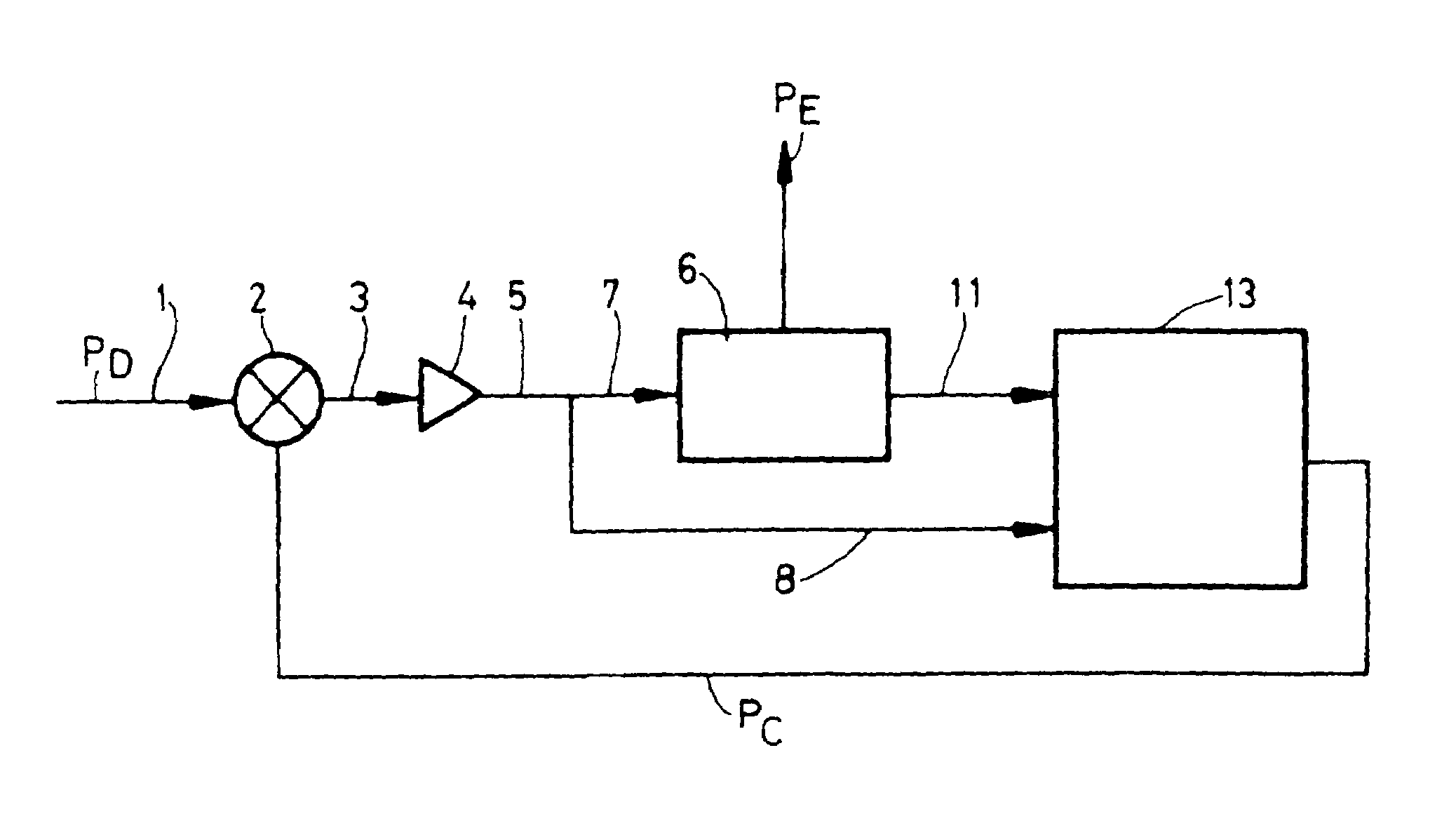
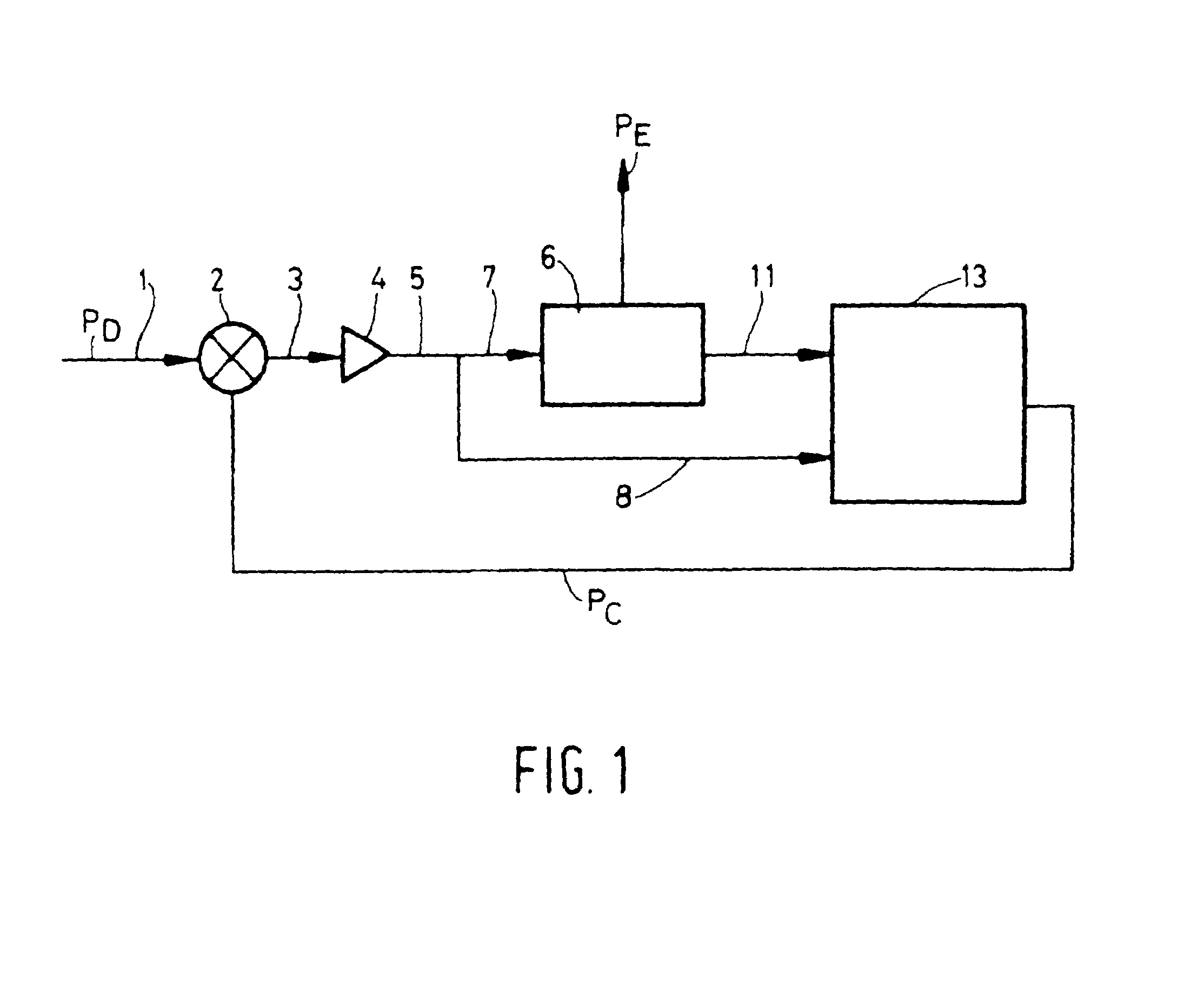
[0030]FIG. 1 diagrammatically illustrates an example of the method according to the present invention. The method according to this embodiment starts from a desired pressure PD, indicated by reference 1, which is to be attained in an ink duct to generate a correct drop ejection. This desired pressure PD is the input signal to a subtracter 2. The desired pressure is translated into a signal 3 for an amplifier 4, which on the basis thereof will feed an actuation voltage 5 to a piezo-electric transducer 6. This voltage is fed to a port 7 of the transducer and, via a connection 8, to a unit 13. In response thereto, the transducer will undergo deformation and attain a pressure PE (effective pressure) in the relevant ink duct. This pressure cannot be measured directly. However, as a result of the pressure PE in the duct the transducer will undergo deformation and thus generate a current which is fed via a connection 11 to unit 13. Using the incoming signals the unit 13 can measure in real...


PUM


Abstract

A method of controlling an inkjet printhead containing a substantially closed duct in which ink is situated, said duct having at least one exit opening for the ink, wherein an actuation pulse is applied to an electro-mechanical transducer so that the pressure in the duct changes in such a manner than an ink drop is ejected from the exit opening, wherein the method further comprises: measuring the electric impedance of the electromechanical transducer and adapting the actuation pulse on the basis of the measured impedance.

Description

[0001]This non-provisional application claims priority under 35 U.S.C. § 119(a) on Patent Application No. 1021013 filed in The Netherlands on Jul. 5, 2002, which is herein incorporated by reference.BACKGROUND OF THE INVENTION[0002]1. Field of the Invention[0003]The present invention relates to a method of controlling an inkjet printhead containing a substantially closed duct in which ink is situated, said duct having an exit opening for the ejection of ink, wherein an actuation pulse is applied to an electromechanical transducer so that the pressure in the duct changes in such a manner than an ink drop is ejected from the exit opening. The present invention also relates to an inkjet printhead suitable for applying the present method and an inkjet printer containing such a printhead.[0004]2. Related Art[0005]A method of this kind is known from EP 0 790 126. The known method is used in a printhead for an inkjet printer, in which the printhead contains a duct plate in which a number of...

Claims


Application Information

Patent Timeline
Patent Type & Authority Patents(United States)
IPC IPC(8): B41J29/393B41J2/045B41J2/055
CPCB41J2/04525B41J2/04541B41J2/04555B41J2/04581B41J2/04588B41J2002/14354
Inventor GRONINGER, MARK ALEXANDERKRUIJT, PIETER GIJSBERTUS MARIAREINTEN, HANSSCHIPPERS, RONALD HERMANSIMONS, JOHANNES MATHIEU MARIE
Owner OCE TECH
Why Eureka
Try Eureka