Trailer Fender with Storage
a fender and trailer technology, applied in the field of trailer fender with storage, can solve the problems of creating buffeting and hazardous aerodynamic conditions, and achieve the effect of easy solid mounting on the trailer or other vehicl
- Summary
- Abstract
- Description
- Claims
- Application Information
AI Technical Summary
Benefits of technology
Problems solved by technology
Method used
Image

Examples
first embodiment
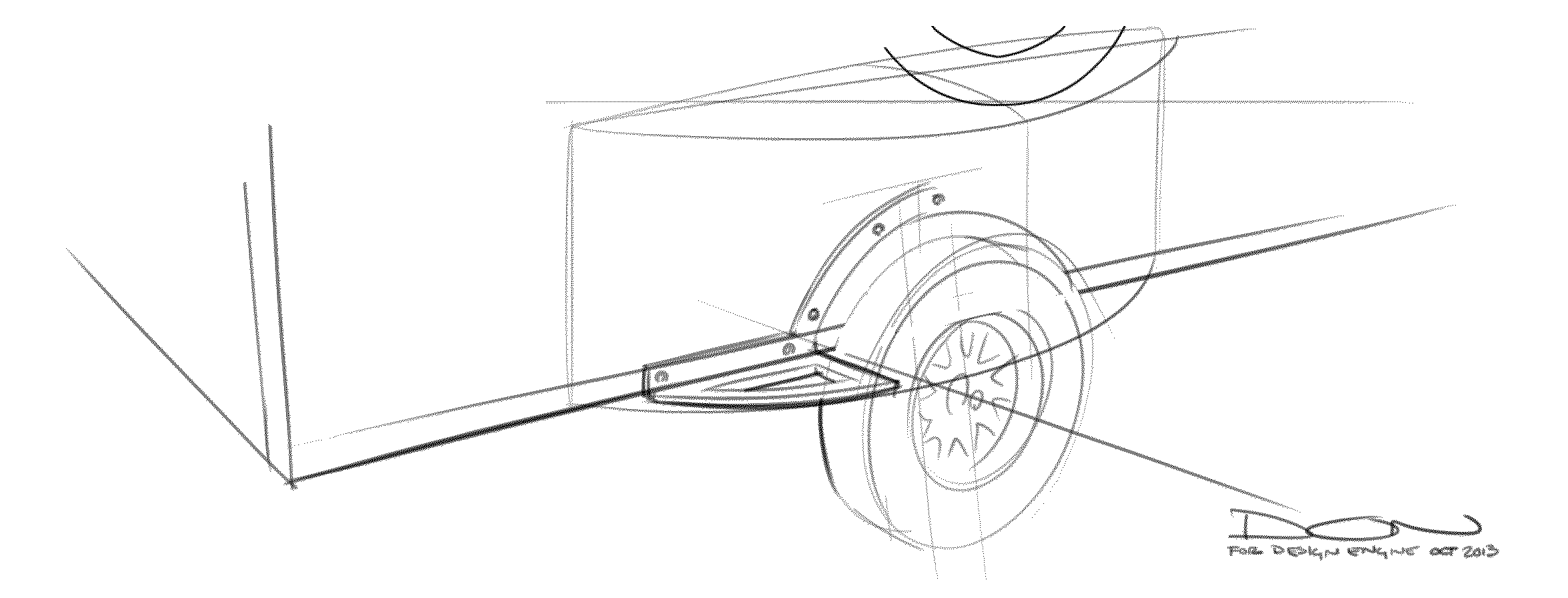
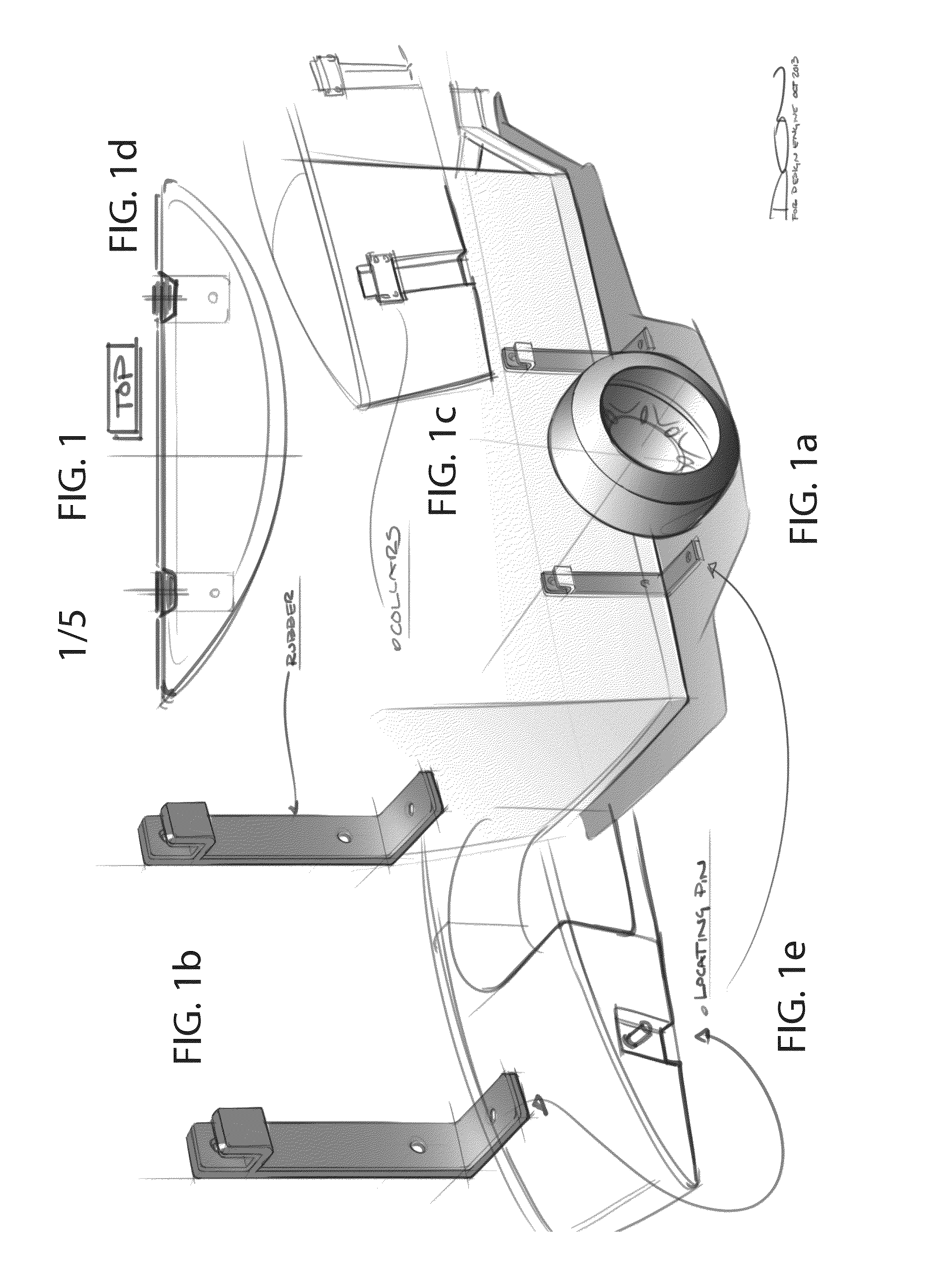
[0041]FIG. 1 depicts the fender and mounting assembly. The mounting sub-assembly comprises two or more vertical L-brackets, as shown in FIGS. 1a and 1b. It is readily realized that the L-bracket may be replaced with a T-bracket, with the extra leg protruding under the vehicle and being attached thereto, for additional stability. For purposed of this Application, the term “L-bracket” shall be defined as including T-brackets or any other bracket which includes an L-shaped portion. The top of the each bracket is hooked upward. Rubberized isolation strips back each bracket and hook. The brackets are pre-mounted to the vehicle. Positioning the brackets is relatively easy and required simple mathematical calculation. The fender body features two rear collars and two lower divots directly underneath each bracket (FIGS. 1c and 1d). The brackets are slid behind the hooks while the divots rest on the lower bracket leg. A peg interface maybe provided for the divots and lower L legs, as shown i...
third embodiment
[0043]The third embodiment, shown in FIG. 3, features a mountable lower frame as a sub-assembly. The frame fits about the wheel well of the vehicle and features an arcuate fender support with lower support ledges (FIG. 3c). The fender body is then mounted upon the fender ledges and fender support (FIGS. 3a and 3b). It should be noted that an appropriate existing fender could be used as a fender support; or, the fender support could be positioned over or in place of an existing fender. The fender body is then fastened to the fender support through conventional means.
fourth embodiment
[0044]The fourth embodiment, shown in FIG. 4, is related to the third in that it utilizes a similar fender support. This embodiment, however, also utilizes one or more back interfaces (FIG. 4a). The depicted interfaces are male and female sliding blocks and frames keyed to fit one another. Any shape whereby the blocks may be keyed to each other, such as a dove-tail design, can be utilized (FIGS. 4c and 4d). One set of blocks or frames is positioned on the vehicle in a manner to interface with the mating set on the fender body (usually the frames being on the vehicle). A rubberized cushion may also be positioned between each block and its attached structure. An L-bracket may also be used in this embodiment (FIG. 4b).
PUM
 Abstract
Description
Claims
Application Information
 - R&D Engineer
- R&D Manager
- IP Professional
- Industry Leading Data Capabilities
- Powerful AI technology
- Patent DNA Extraction
Browse by: Latest US Patents, China's latest patents, Technical Efficacy Thesaurus, Application Domain, Technology Topic.
© 2024 PatSnap. All rights reserved.Legal|Privacy policy|Modern Slavery Act Transparency Statement|Sitemap