Power system and method of operating a power system

a power system and power system technology, applied in the field of power systems, can solve problems such as system start-up, and achieve the effect of simple and easy control

Active Publication Date: 2015-04-30
HITACHI ENERGY SWITZERLAND AG
View PDF2 Cites 25 Cited by
  • Summary
  • Abstract
  • Description
  • Claims
  • Application Information

AI Technical Summary

Benefits of technology

[0004]An object of the present invention is to eliminate or at least mitigate the problems of prior art

Problems solved by technology

However, they suffer from the drawback that the best sites for generation are geographically located around the tropics, far from major load centers.
Also startup of the system provides

Method used


Image

  • Power system and method of operating a power system
  • Power system and method of operating a power system

Examples


Embodiment Construction

[0014]In the following, a detailed description of a power system and a method of operating such a system will be given.

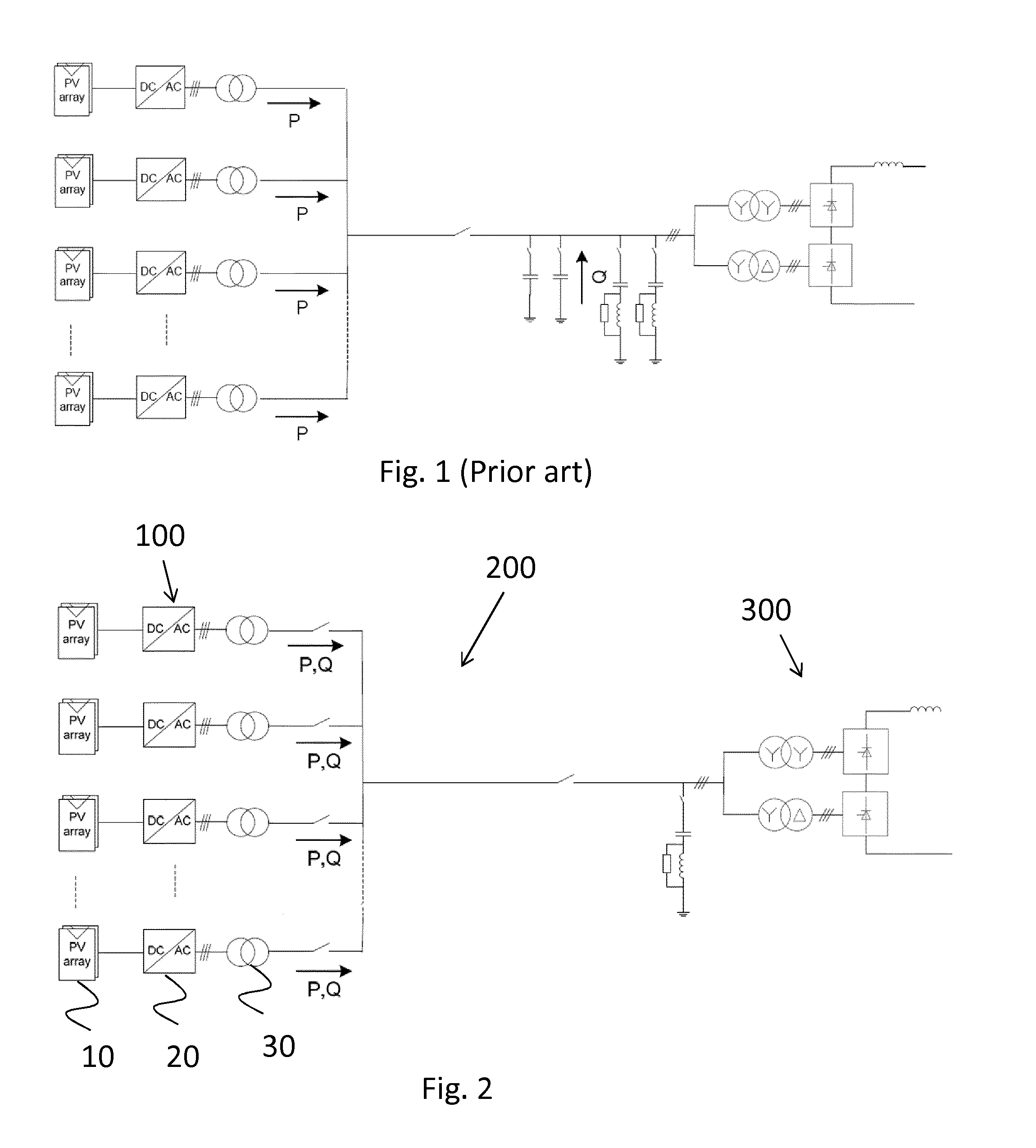
[0015]FIG. 1 has been described in the background art section and will not be further commented herein.

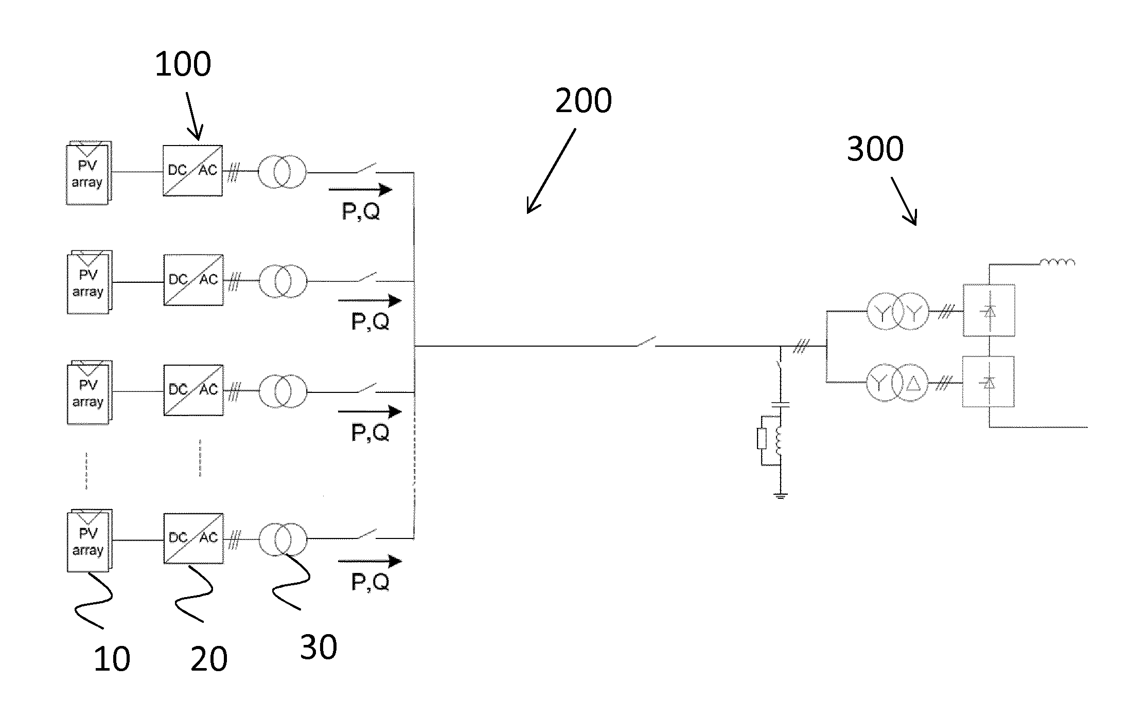
[0016]With reference to FIG. 2, a power system comprises a power generating plant, generally designated 100, having a plurality of power generators 10 and a plurality of inverters 20, wherein each inverter is connected to a respective power generator. In large scale power generating plants, there can be from 100 inverters up to as many as 1000 inverters or even more. Thus, the power generating plant 100 is a microgrid with a localized grouping of electricity generation.

[0017]In a preferred embodiment, the power generators are comprised in a large photovoltaic power station and each power generator 10 is a photovoltaic (PV) array. A photovoltaic power station, also known as a solar park or solar farm, is a large-scale photovoltaic system designed for the supply of p...


PUM


Abstract

A power system includes a power generating plant including a plurality of power generators, and an AC collection grid adapted to interconnect the power generating plant and an HVDC converter station. The AC collection grid is adapted to operate outside network regulations, whereby advantages such as simplified control and electronics are achieved. A method of operating a power system is also provided.

Description

TECHNICAL FIELD[0001]The present invention relates generally to a power system and more particularly to a power system comprising a plurality of power generators connected to an HVDC converter station. The present invention also relates to a method of operating such a power system.BACKGROUND ART[0002]Photovoltaic (PV) energy generation systems are attractive from the point of view in that they offer a way of generating electricity without CO2 emissions and other drawbacks of conventional energy sources. However, they suffer from the drawback that the best sites for generation are geographically located around the tropics, far from major load centers. For this reason long-distance power transmissions are likely to be necessary if photovoltaics should be employed on a large scale.[0003]For very long distances and subsea transmission the preferred method is currently high voltage direct current (HVDC) transmission. The most intuitive way of creating a PV power plant with HVDC connectio...

Claims


Application Information

Patent Timeline
IPC IPC(8): H02J3/38H02M7/42H02J1/12H02M1/12
CPCH02J3/38H02J1/12H02M7/42H02M1/12
Inventor NORRGA, STAFFANMARINOPOULOS, ANTONISPAPASTERGIOU, KONSTANTINOSBAKAS, PANAGIOTIS
Owner HITACHI ENERGY SWITZERLAND AG
Why Eureka
Try Eureka