Power-sharing charging system, charging device, and method for controlling the same

a charging system and power-sharing technology, applied in the direction of charging stations, battery/fuel cell control arrangements, transportation and packaging, etc., can solve the problems of limited power supply from the system to such charging devices or charging systems, limited hardware and policy limits,

Active Publication Date: 2015-04-30
KOREA INST OF ENERGY RES
View PDF10 Cites 22 Cited by
  • Summary
  • Abstract
  • Description
  • Claims
  • Application Information

AI Technical Summary

Benefits of technology

[0018]As described above, an aspect of the present invention is advantageous in that at least two charging devices, which have limited power capacities, share power with each other so that one charging device can supply charging power more than the limited power capacity.
[0019]Another

Problems solved by technology

However, an automobile that does not include such a generator as the fuel cell needs to be supplied with electric energy using an electric energy storage device, such as a battery.
Such batteries can store only a limited amount of energy, so that automobiles need to charge their batteries frequently.
However, there is a limit on the amount of power that can be supplied from the system to such charging devices or charging systems.
Such limits largely occur in terms of hardware and policy.
Such a hardware-related limit on power capacity places a limit on the amount of power that can be supplied from the system to a charging device or a charging system.
In terms of policy, which is another aspect, a similar limit may occur.
The process of charging automobiles instantly require a large amount of power, and, in terms of the system's management, such power peaks may be factors that disturb the system.
The above-mentioned limit on power supply may be a factor that interferes with efficient operation of a charging device or a charging system.
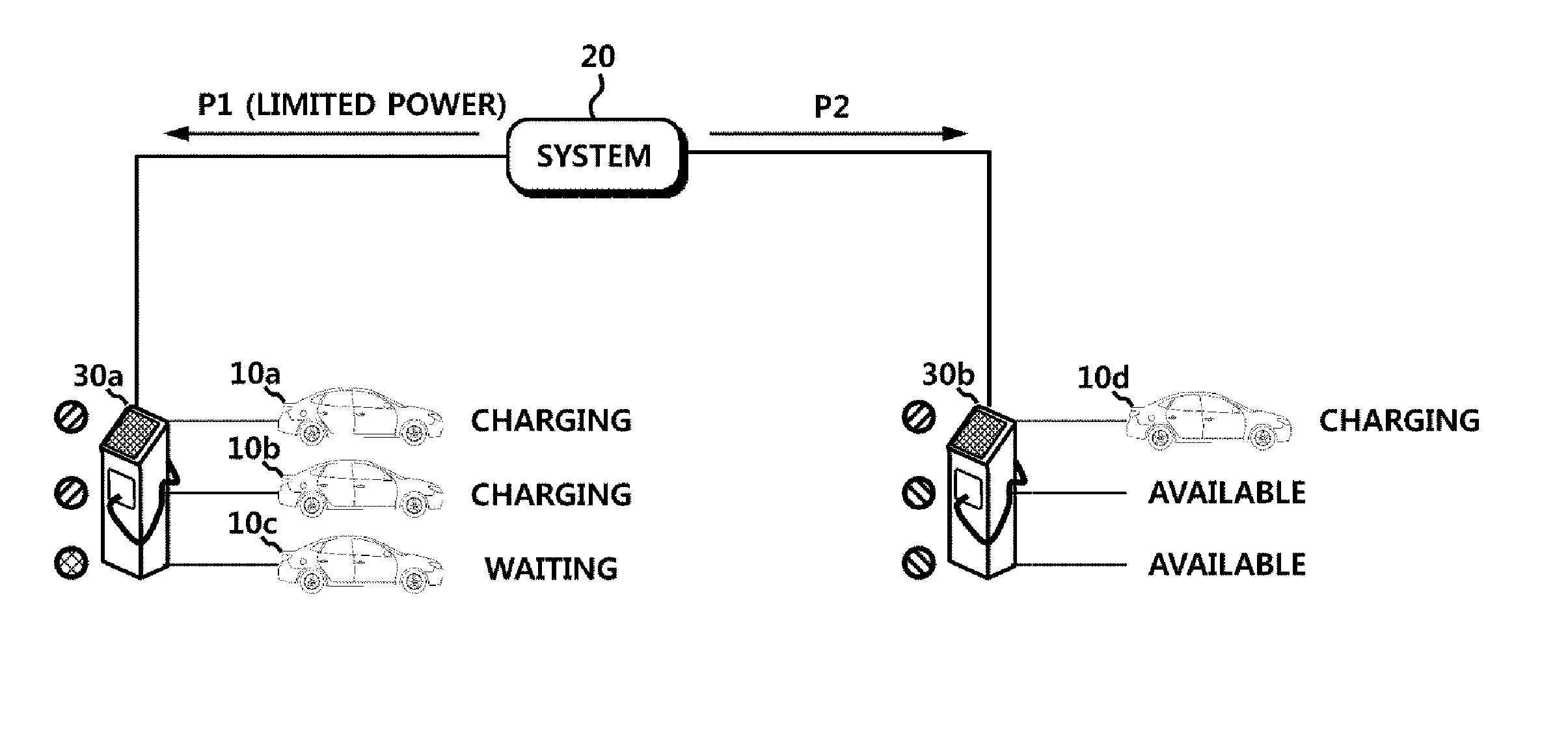
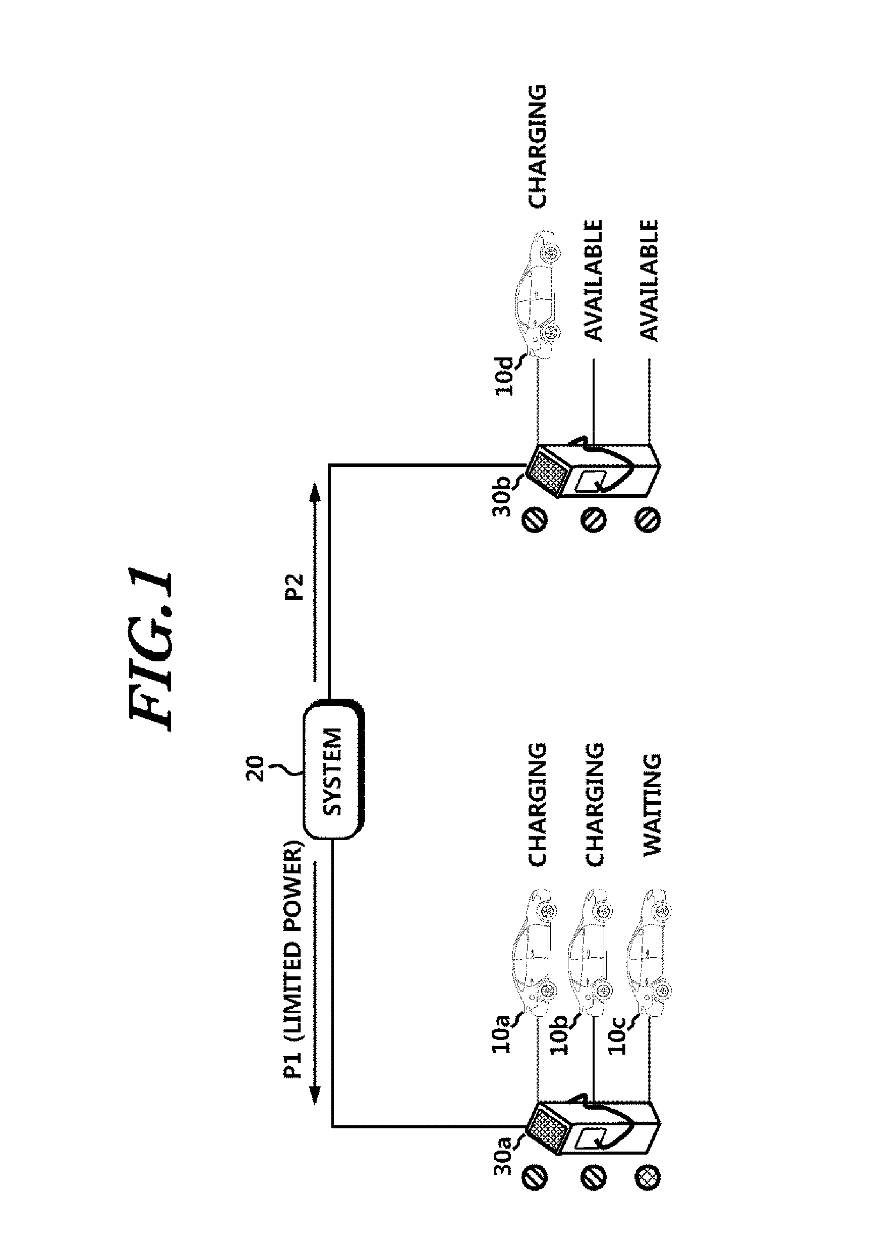
It will be assumed for example that two charging devices are installed in a charging system, a number of automobiles are connected to charging device B among them, and no automobile is connected to charging device A. Then, the limited power capacity may

Method used


Image

  • Power-sharing charging system, charging device, and method for controlling the same
  • Power-sharing charging system, charging device, and method for controlling the same
  • Power-sharing charging system, charging device, and method for controlling the same

Examples


Embodiment Construction

[0041]Hereinafter, exemplary embodiments of the present invention will be described in detail with reference to the accompanying drawings. In the following description, the same elements will be designated by the same reference numerals although they are shown in different drawings. Further, in the following description of the present invention, a detailed description of known functions and configurations incorporated herein will be omitted when it may make the subject matter of the present invention rather unclear.

[0042]In addition, terms, such as first, second, A, B, (a), (b) or the like may be used herein when describing components of the present invention. These terms are merely used to distinguish one structural element from other structural elements, and a property, an order, a sequence and the like of a corresponding structural element are not limited by the term. It should be noted that if it is described in the specification that one component is “connected,”“coupled” or “j...


PUM


Abstract

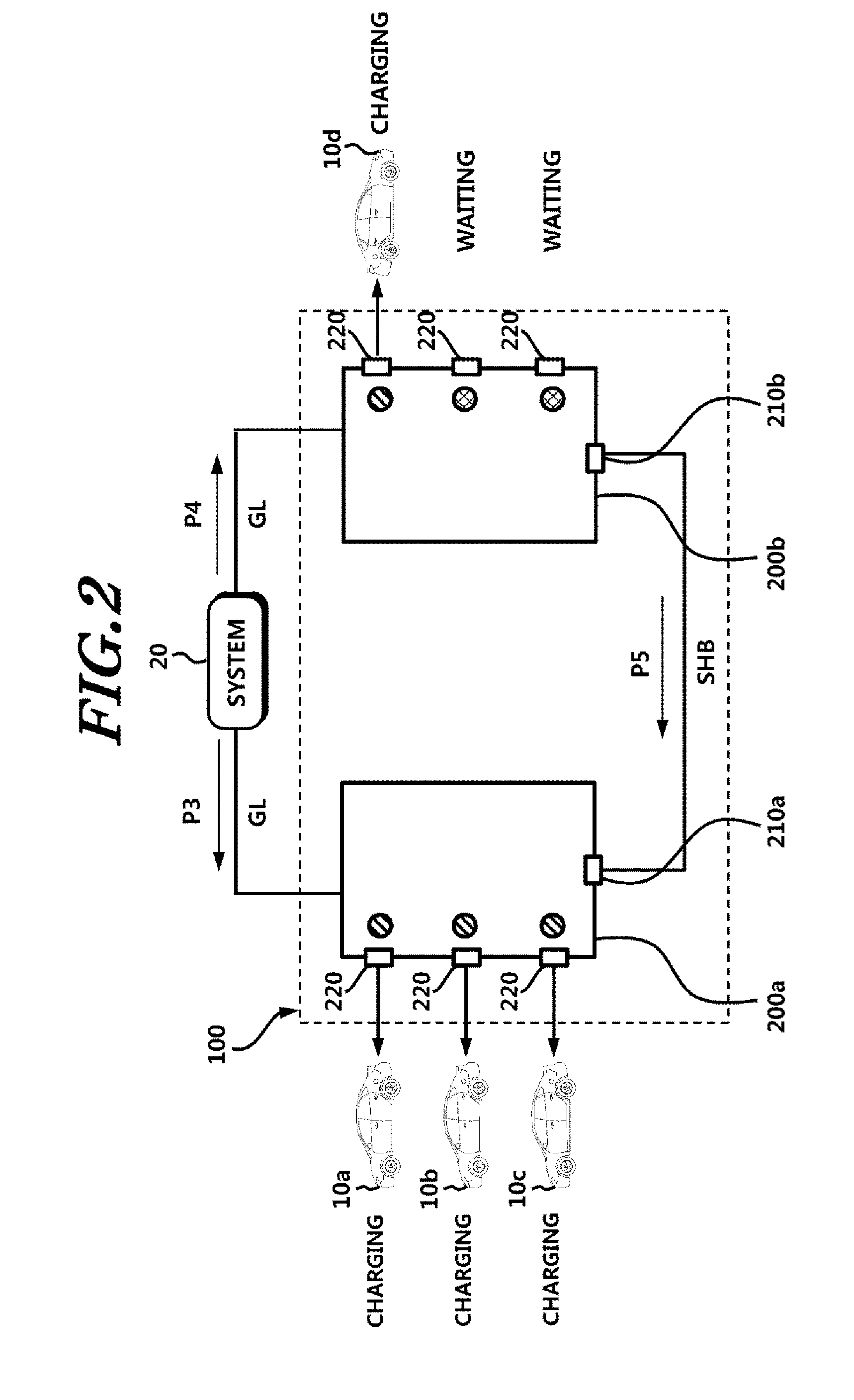
The present disclosure provides a charging system including: at least two charging devices including at least two output units configured to supply connected automobiles with charging power, a first bus electrically connected to the output units and configured to transfer charging power to the output units, and a power processing unit configured to process power, which is supplied from a power source, using a first capacity and supply the first bus with the processed power; and a second bus configured to connect a first bus of a first charging device and a first bus of a second charging device, wherein, when a total capacity of charging power supplied to automobiles connected to the first charging device exceeds the first capacity, a part or all of lacking capacity is supplied via the second bus.

Description

CROSS-REFERENCE TO RELATED APPLICATION[0001]This application claims priority from and the benefit under 35 U.S.C. §119(a) of Korean Patent Application No. 10-2013-0127520, filed on Oct. 25, 2013, and of Korean Patent Application No. 10-2014-0081514, filed on Jun. 30, 2014, which are hereby incorporated by reference for all purposes as if fully set forth herein.BACKGROUND OF THE INVENTION[0002]1. Field of the Invention[0003]The present invention relates to a charging system, a charging device, and a method for controlling the same and, more particularly, to charging devices sharing power with each other.[0004]2. Description of the Prior Art[0005]Increasing attention to environments has been followed by extensive development of automobiles that move using electric energy. Such automobiles include electric automobiles, which are solely powered by electricity, and hybrid-type automobiles, which include both gasoline engines and electric motors.[0006]In order for an automobile to run usi...

Claims


Application Information

Patent Timeline
IPC IPC(8): B60L11/18
CPCB60L11/1824Y02T90/14Y04S10/126Y04S30/14Y02T10/7072B60L53/63B60L53/665B60L53/11B60L58/13B60L58/15B60L53/305Y02E60/00Y02T10/70Y02T90/12Y02T90/167Y02T90/16B60L53/30
Inventor SUNG, YOON DONGHAN, SU BINOH, SEA SEUNGCHAE, SU YONGKIM, GYU DUKYU, SEUNG WEONSONG, YUJINLEE, ILOUNPARK, SUKIN
Owner KOREA INST OF ENERGY RES
Why Eureka
Try Eureka