Control circuit module for power factor corrector

Inactive Publication Date: 2015-04-30
ASIAN POWER DEVICES
View PDF1 Cites 4 Cited by
  • Summary
  • Abstract
  • Description
  • Claims
  • Application Information

AI Technical Summary

Benefits of technology

[0007]An object of the present disclosure is to provide a control circuit modular for a power factor corrector to make the operation mode of the inductor current is converted from the boundary co

Problems solved by technology

In general, the high-switching losses are increased to reduce system ef

Method used


Image

  • Control circuit module for power factor corrector
  • Control circuit module for power factor corrector
  • Control circuit module for power factor corrector

Examples


Example

[0015]Reference will now be made to the drawing figures to describe the present invention in detail.

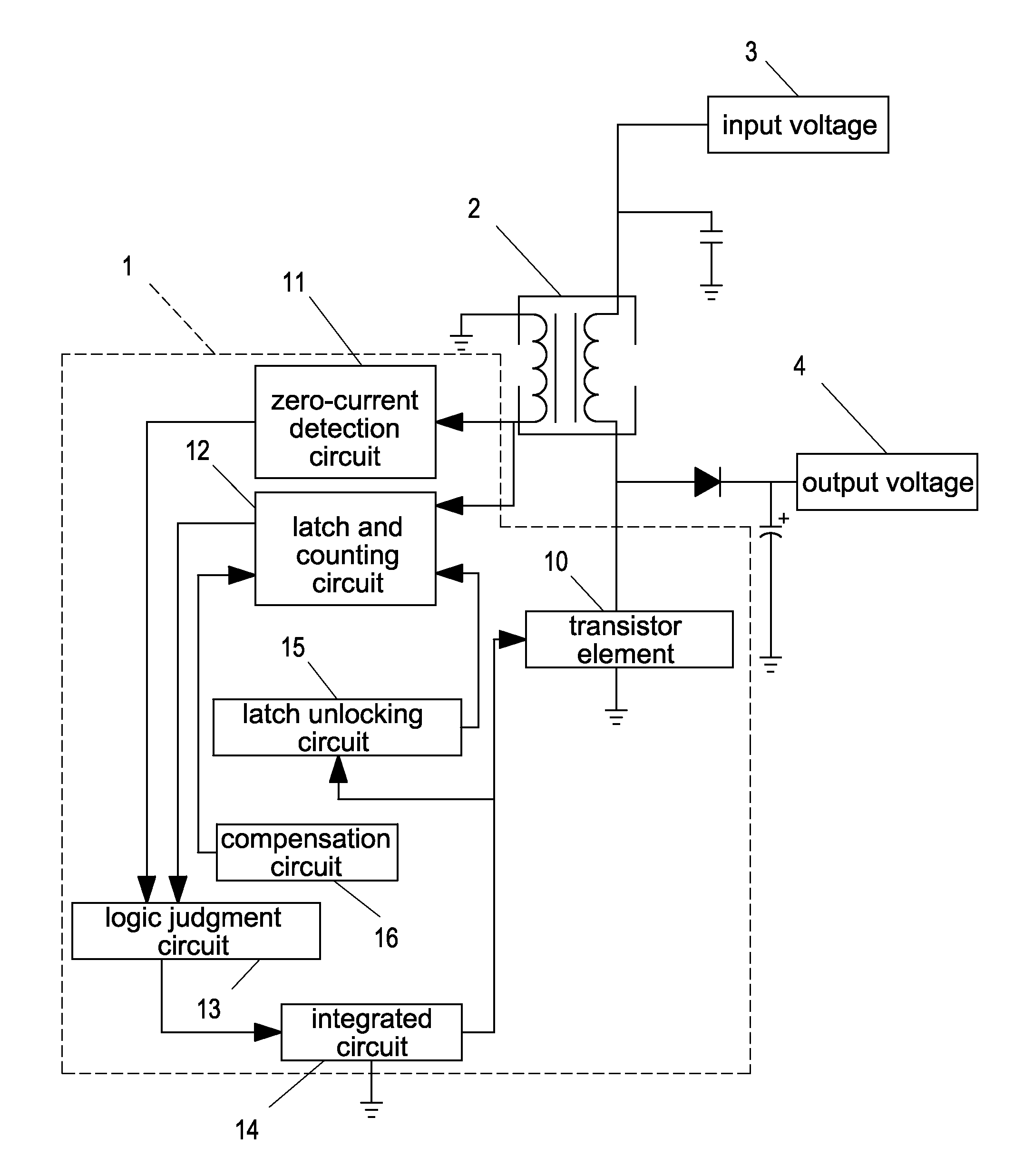
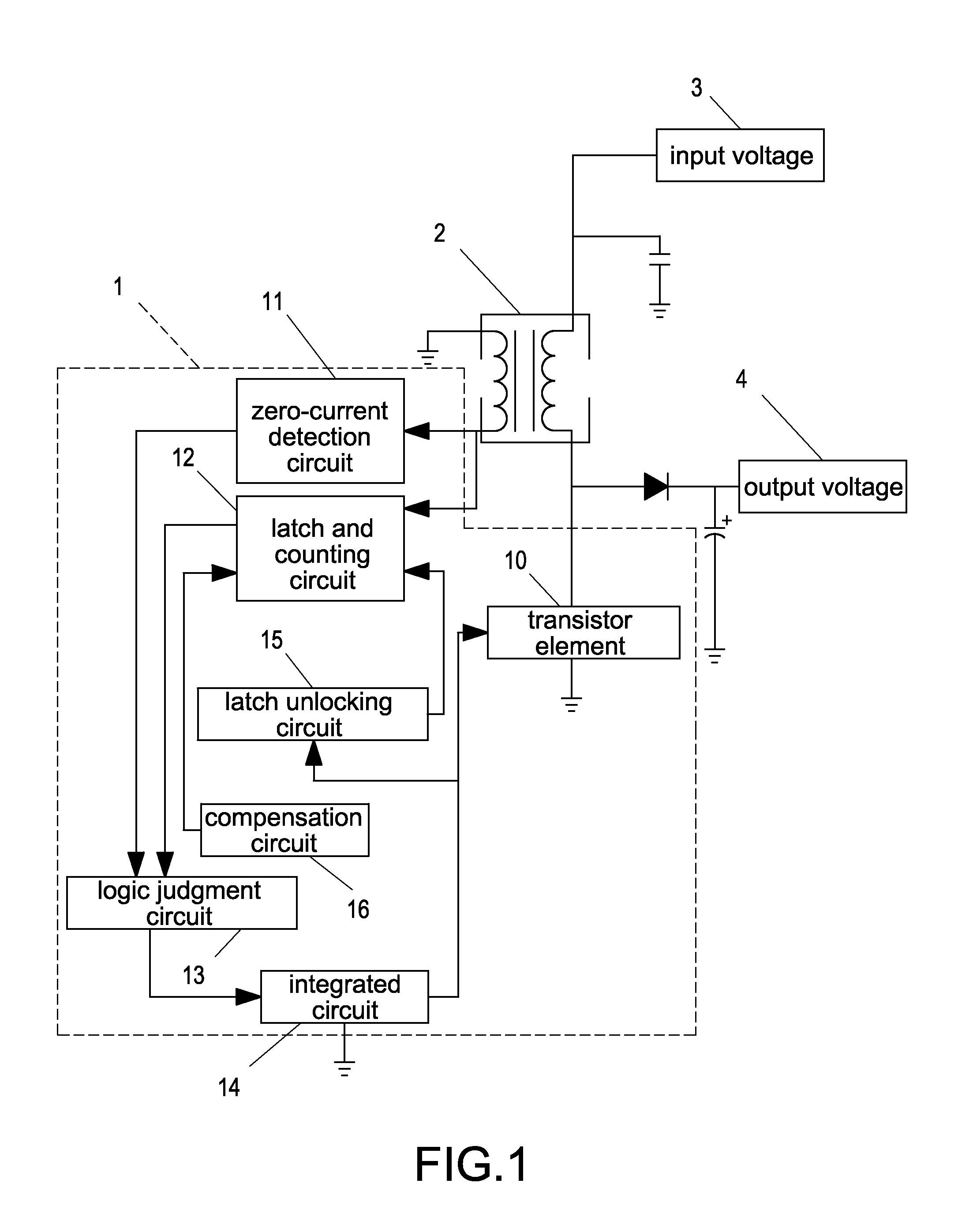
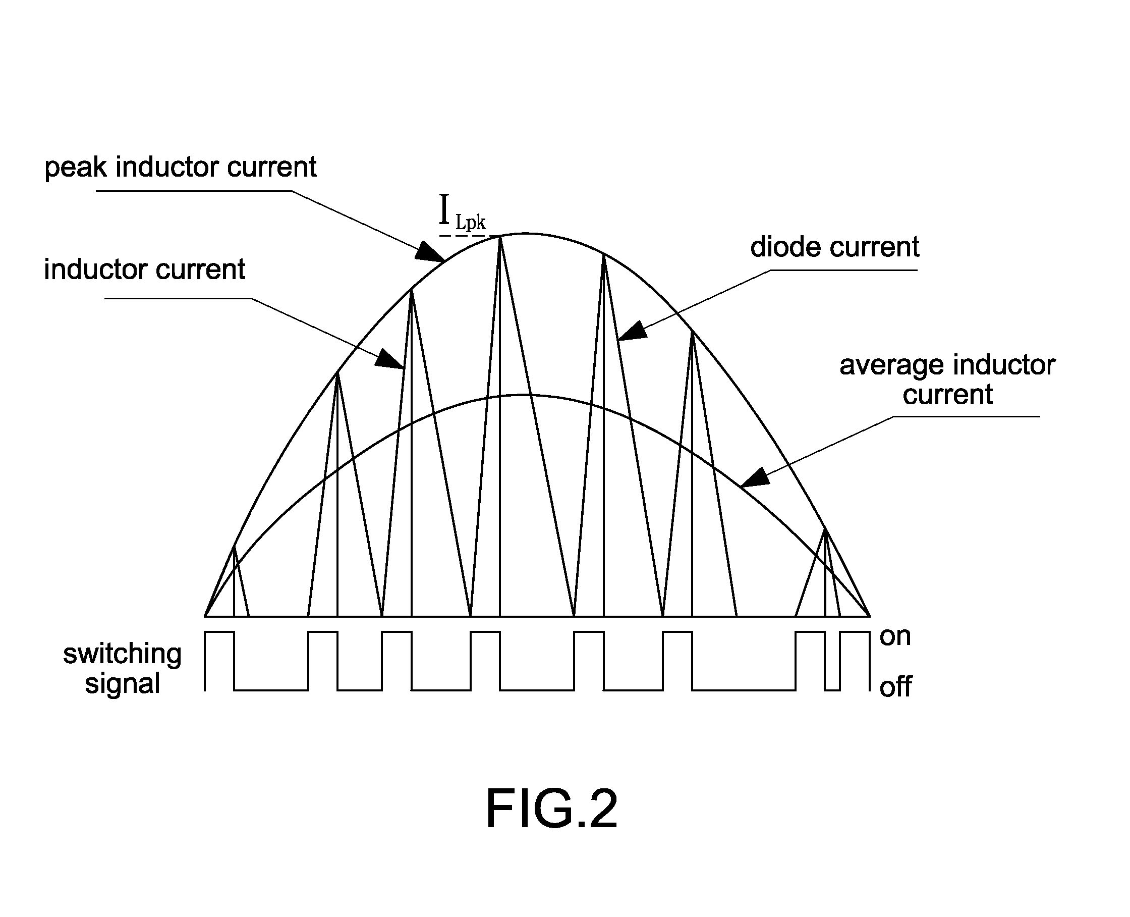
[0016]Reference is made to FIG. 1 and FIG. 2 which are circuit block diagram of a control circuit module and a waveform of showing an inductor current according to the preferred embodiment of the present disclosure. The control circuit module 1 is coupled to an inductor element 2, and the inductor element 2 is coupled to an input voltage 3 and an output voltage 4. In particular, the inductor element 2 can be a choke component.

[0017]The control circuit module 1 has a transistor element 10, a zero-current detection circuit 11, a latch and counting circuit 12, a logic judgment circuit 13, an integrated circuit 14, a latch unlocking circuit 15, and a compensation circuit 16. In particular, the transistor element 10 can be a metal-oxide-semiconductor field-effect transistor (MOSFET), and the integrated circuit 14 can be a microprocessor (MPU) or a microcontroller (MCU).

[0018]The transistor...


PUM


Abstract

A control circuit module for a power factor corrector is provided to convert the operation mode of the inductor current from the boundary conduction mode (BCM) to the discontinuous conduction mode (DCM) when a transistor element is operated under the valley inductor current, thus reducing the switching frequency and increasing system efficiency, also to maintain the operation mode of the inductor current in the BCM when the transistor element is operated under the peak inductor current, thus maintaining system efficiency.

Description

BACKGROUND[0001]1. Technical Field[0002]The present disclosure relates generally to a control circuit module, and more particularly to a control circuit module is applied to a power factor corrector.[0003]2. Description of Related Art[0004]With the development of technology and economy, the demand of switch converters is increased. In recent years, most of electronic devices and power converters thereof will be developed toward the trend of light-weight, thin, small in size. Accordingly, the switching power converter will gradually replace the conventional linear converter to become a mainstream power converter due to smaller size, lighter weight, higher efficiency, and better quality of the switching power converter.[0005]The power factor corrector can be operated in a continuous conduction mode (CCM), a discontinuous conduction mode (DCM), and a boundary conduction mode (BCM) according to the required applications.[0006]In general, the high-switching losses are increased to reduce...

Claims


Application Information

Patent Timeline
IPC IPC(8): H02M3/157H02M1/00H02M1/42
CPCH02M3/157H02M1/4225Y02B70/10Y02P80/10H02M1/0012H02M1/0032H02M1/0054
Inventor YANG, CHIH-LUNGHUNG, TSUNG-LIANG
Owner ASIAN POWER DEVICES
Why Eureka
Try Eureka