DC-DC regulator with switching frequency responsive to load

Active Publication Date: 2005-08-25
INFINEON TECH AMERICAS
View PDF39 Cites 46 Cited by
  • Summary
  • Abstract
  • Description
  • Claims
  • Application Information

AI Technical Summary

Benefits of technology

[0024] According to one preferred embodiment, the oscillator includes a controllable current source which feeds or diverts current from a timing capacitor to determine the oscillator frequency. An error amplifier senses the output voltage of the switching regulator and compares it to a reference voltage. The error amplifier is a transconductance amplifier having an output series resistor and capacitor which provides a means for compensating the converter regulator loop. The error amplifier's output current is mirrored in a current mirror and the current is supplied to the clock oscillator circuit to affect the charge/discharge rate of the oscillator capacitor. During moderate load conditions, the error amplifier current is near zero, so the switching frequency is constant. If the error output voltage decreases below a preset value, because of li

Problems solved by technology

This causes the error amplifier to sink current from the clamp which reduc

Method used


Image

  • DC-DC regulator with switching frequency responsive to load
  • DC-DC regulator with switching frequency responsive to load
  • DC-DC regulator with switching frequency responsive to load

Examples


Example

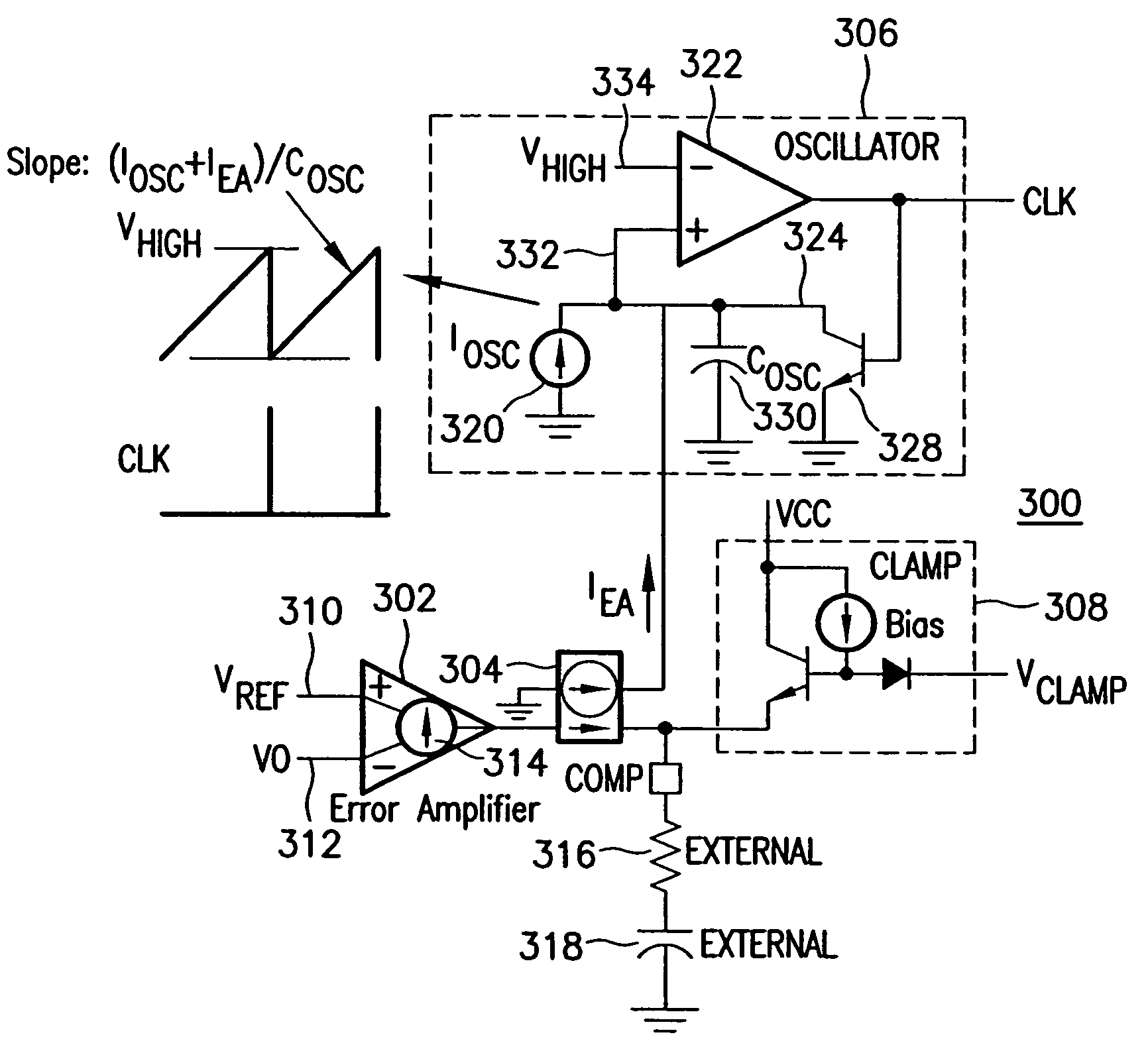
[0032] Referring now to FIG. 3, there is shown a first embodiment of a variable frequency gate drive oscillator according to the invention, generally designated at 300. This is intended to be implemented using standard integrated circuit fabrication techniques and circuit designs, and therefore the description will be limited to the system architecture and functionality. Those skilled in the art will readily understand how the invention is to be implemented from the following description using any suitable circuit design.

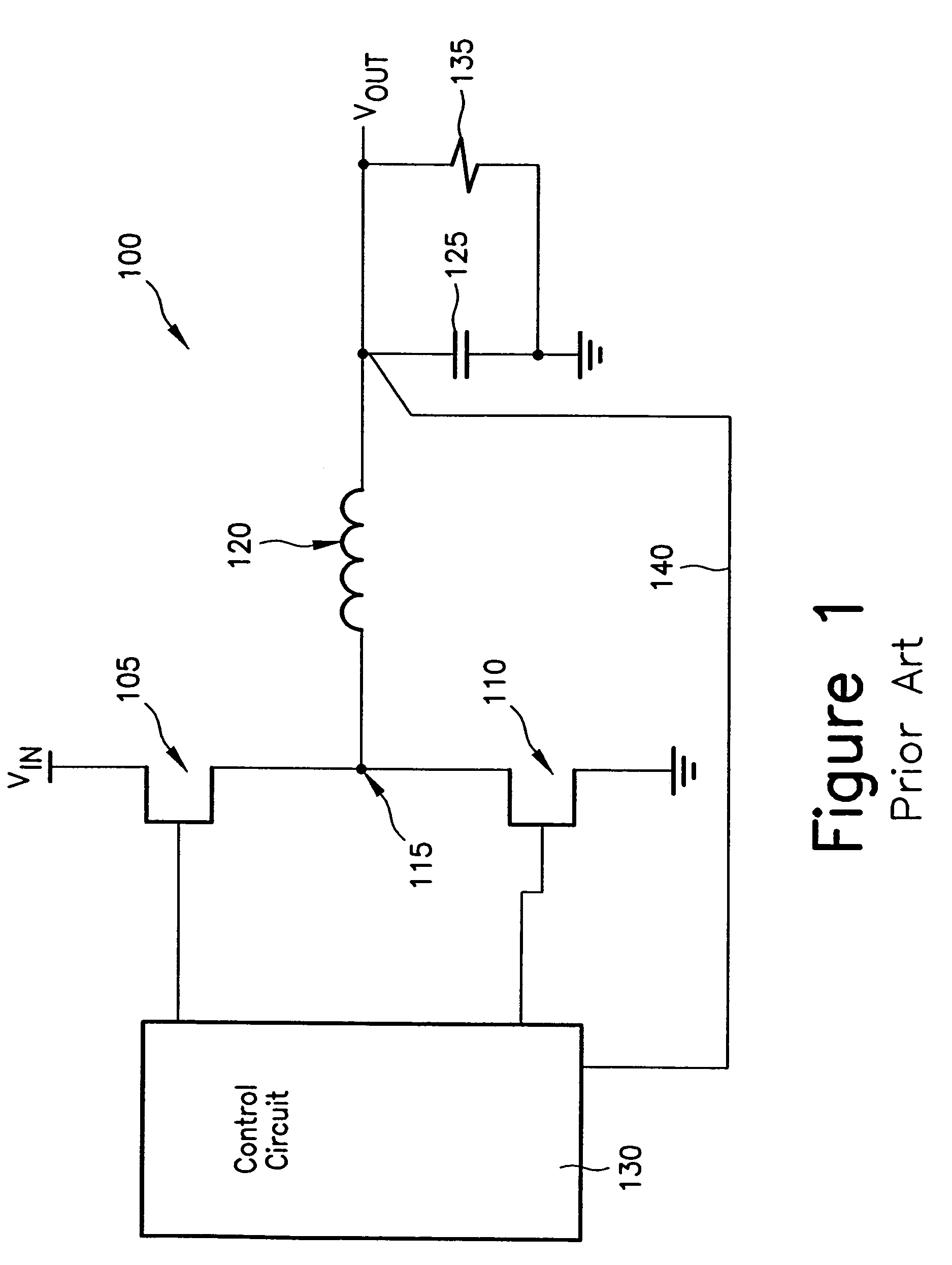
[0033] Frequency controller 300 includes an error amplifier 302, a current mirroring circuit 304, a variable frequency oscillator 306, and a clamping circuit 308. Error amplifier 302 is a transconductance amplifier which receives a reference signal VREF at an input 310, and an error signal VO at a second input 312, the latter representing a feedback signal from the power supply regulation loop 140 (see FIG. 1). A load circuit for error amplifier 302 comprised of a ...


PUM


Abstract

A switch mode power supply in which the switching frequency is controlled by an oscillator having a nominal frequency, and having an error amplifier to provide an output signal which represents departure of the power supply output from a nominal value, and which functions by adjusting the frequency of the oscillator to a frequency which is higher or lower than the nominal frequency according to the value of the error amplifier output signal.

Description

RELATED APPLICATION [0001] The present application is based on and claims the benefit of U.S. Provisional Application No. 60 / 546,119, filed on Feb. 19, 2004, entitled DC-DC REGULATOR WITH SWITCHING FREQUENCY RESPONSIVE TO LOAD, the entire contents of which are expressly incorporated herein by reference.FIELD OF THE INVENTION [0002] The present invention relates to switch mode power supplies in which the conventional pulse width modulation (PWM) control of the switching devices is modified to vary the switching frequency so that for light loads, the drive frequency is decreased, and for step load increases, the drive frequency is increased. BACKGROUND OF THE INVENTION [0003] Switched power supplies have numerous applications in electronic devices and motor drives, and several basic types are well known to those skilled in the art. For purposes of illustration, the invention will be described in the context of a conventional DC-to-DC buck converter that accepts a DC input voltage and ...

Claims


Application Information

Patent Timeline
IPC IPC(8): G05F1/40H02M3/156
CPCH02M3/1584H02M3/156G05F1/10G05F1/40
Inventor WALTERS, MIKE
Owner INFINEON TECH AMERICAS
Why Eureka
Try Eureka