Motor system

Inactive Publication Date: 2012-08-02
HONDA MOTOR CO LTD
View PDF6 Cites 13 Cited by
  • Summary
  • Abstract
  • Description
  • Claims
  • Application Information

AI Technical Summary

Benefits of technology

[0097]According to the fourteenth aspect of the present invention, when the velocity of the shifting magnetic field is greater than the upper velocity limit, the drive voltage is generated according to the voltage command value by performing a 2-phase modulation, which makes it possible to reduce

Problems solved by technology

Structurally, the motor disclosed in Japanese Patent Laid-open No. 2008-67592 must have a first soft magnetic material array composed of a plurality of the first cores and a second soft magnetic material array composed of a plurality of the second cores; therefore, it would be a problem that the motor has to be made large in size.
According to the structure of the motor disclosed in the patent document,

Method used


Image

  • Motor system
  • Motor system
  • Motor system

Examples


Example

First Embodiment

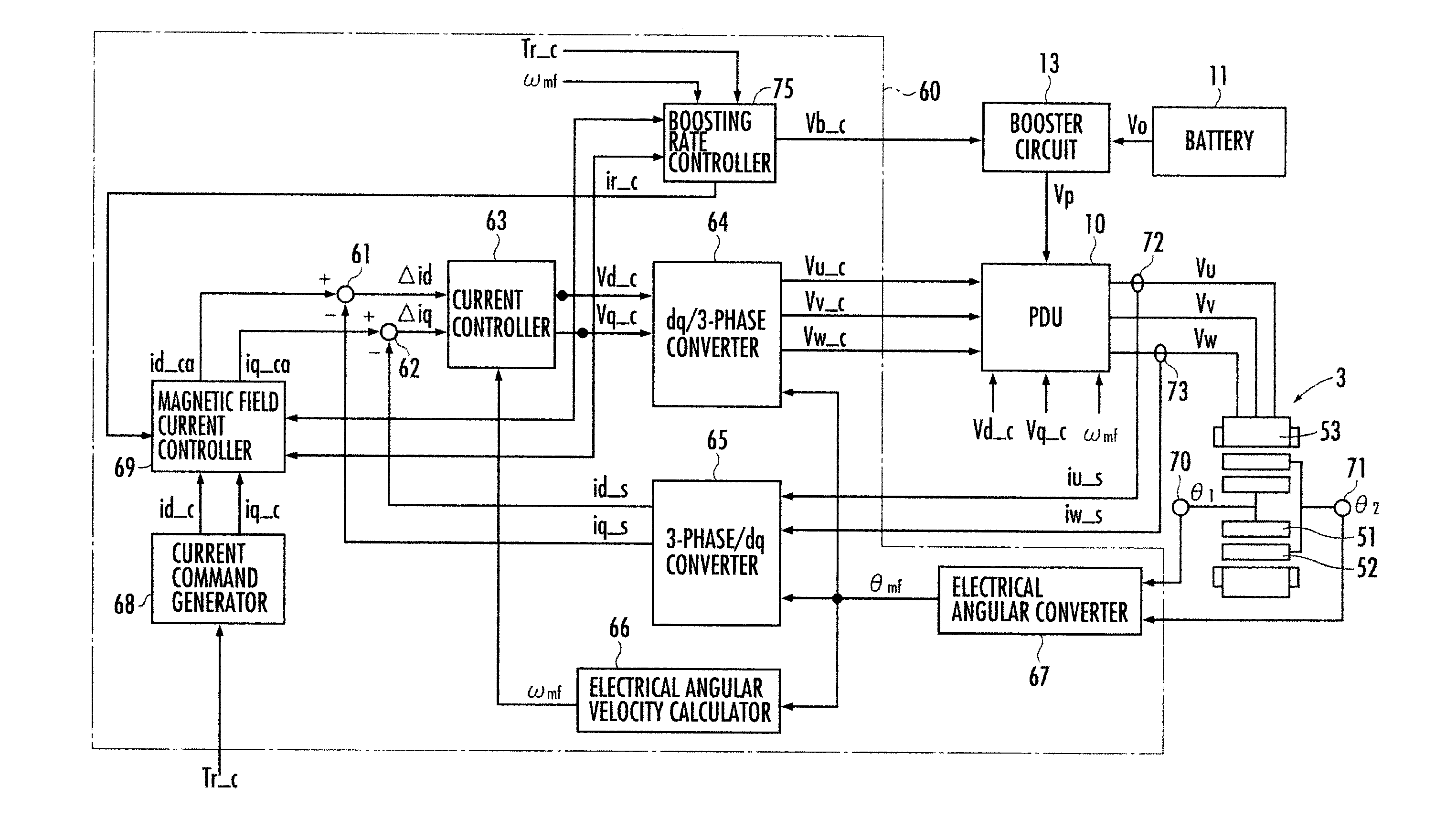
[0148]Firstly, a first embodiment of the first process and the second process performed by the ECU60 will be described. In the first embodiment, the boosting rate controller 75 determines which process in the first process and the second process should be performed in priority according to a torque-loss correlation map illustrated in FIG. 4.

[0149]The correlation map of FIG. 4 having the loss (Loss) being set as the vertical axis and the torque (Tr) being set as the horizontal axis exhibits a loss (first loss) a1 occurred in performing only the first process and a loss (second loss) b1 occurred in performing only the second process at an electrical angular velocity greater than a predefined upper velocity limit in order to acquire the required torque of the rotary machine 3.

[0150]In the correlation map of FIG. 4, when the torque is not greater than Tr10, the first loss occurred in performing the first process is smaller than the second loss occurred in performing the ...

Example

Second Embodiment

[0153]Hereinafter, a second embodiment of the first process and the second process performed by the ECU60 will be described. In the second embodiment, the boosting rate controller 75 determines the magnetic field weakening setting for the first process and the boosting rate setting for the second process when both of the first process and the second process are performed according to a boosting rate-loss correlation map illustrated in FIG. 5.

[0154]The correlation map of FIG. 5 having the loss (Loss) being set as the vertical axis and the boosting rate (Rate) being set as the horizontal axis exhibits the variation of loss when both of the first process (magnetic field weakening process) and the second process (voltage boosting process) are performed on condition that the magnitude (√{square root over ( )}(Vd—c2+Vq—c2)) of the vector sum of the d-axis voltage command value Vd—c and the q-axis voltage command value Vq—c is greater than the upper voltage limit Vulmt in ...

Example

Third Embodiment

[0158]Hereinafter, together with the first embodiment and the second embodiment or independent from the first embodiment and the second embodiment, a generation process of the drive voltages Vu, Vv and Vw performed by the PDU 10 will be described.

[0159]The PDU 10 generates the drive voltages Vu, Vv and Vw according to a 3-phase modulation when the electrical angular velocity ωmf is equal to or lower than a predefined upper velocity limit. When the electrical angular velocity ωmf is greater then the upper velocity limit, the PDU 10 generates the drive voltages Vu, V1 and Vw according to a 2-phase modulation. Thereby, it is possible to reduce the switching frequency of the switching elements (transistor and the like) in the inverter circuit of the PDU 10 in a high-velocity rotating region, and consequently to reduce the switching loss.

[0160]Hereinafter, with reference to FIG. 6 to FIG. 8, the generation process of the drive voltages Vu, Vv and Vw according to the 2-pha...


PUM


Abstract

A motor system comprises a motor (3), wherein the ratio of the number of armature magnetic poles of a stator (53), the number of magnetic poles of a first rotor (51), and the number of cores of a second rotor (52) is set to 1:m:(1+m)/2, and en ECU (60) that generates a d-axis voltage command value (Vd<sub2>—</sub2>c) and a q-axis voltage command (Vq<sub2>—</sub2>c) according to a torque command value (Tr_c), and corrects the voltage command values so as to generate a magnetic field weakening current which reduces the magnetic flex of the magnetic poles of the first rotor when the magnitude of the vector sum of the voltage command values is greater than an upper voltage limit (Vulmt) set according to an output voltage (Vo) of a battery (11).

Description

BACKGROUND OF THE INVENTION[0001]1. Field of the Invention[0002]The present invention relates to a motor system disposed with a motor having a plurality of movers and a controller for controlling the motor.[0003]2. Related Background Art[0004]Hitherto, as a motor having a plurality of movers, for example, there has been known a rotary machine provided with a first rotor connected to a first rotary shaft, a second rotor connected to a second rotary shaft, and a stator (for example, refer to Japanese Patent Laid-open No. 2008-67592).[0005]In the motor disclosed in Japanese Patent Laid-open No. 2008-67592, the first rotary shaft and the second rotary shaft are disposed concentrically, and the first rotor and the second rotor and the stator are disposed along the radial direction of the first rotary shaft from the inner side in sequence as mentioned. The first rotor is disposed with a plurality of first permanent magnets and second permanent magnets arranged along the circumferential di...

Claims


Application Information

Patent Timeline
IPC IPC(8): H02P21/14H02P6/08
CPCH02K49/06H02P21/0089H02P21/06
Inventor KASAOKA, KOTAABE, NORIYUKIAKUTSU, SHIGEMITSUIWASHITA, HIDEAKI
Owner HONDA MOTOR CO LTD
Why Eureka
Try Eureka