Package, resonation device, oscillator, electronic device, and moving object

a resonator and oscillator technology, applied in the field of packaging, resonator, oscillator, electronic device, moving object, can solve the problems of reducing the resonation characteristics of the piezoelectric resonator element, hindering the further reduction of the planar size,

Active Publication Date: 2015-04-30
SEIKO EPSON CORP
View PDF6 Cites 18 Cited by
  • Summary
  • Abstract
  • Description
  • Claims
  • Application Information

AI Technical Summary

Benefits of technology

[0063]In this configuration, the moving object of this configuration includes the resonation device according to any one of the applic...

Problems solved by technology

As a result, in the piezoelectric device configured in the above-described manner, there is a concern that a further reduction in a planar size may be hindered due to restrictions (a wiring rule such as a pattern width, a gap between patterns, a distance between a contour and a pattern) of the routing of the first wiring pattern and the second wiring pattern.
However,...

Method used


Image

  • Package, resonation device, oscillator, electronic device, and moving object
  • Package, resonation device, oscillator, electronic device, and moving object
  • Package, resonation device, oscillator, electronic device, and moving object

Examples


first embodiment

[0075]First, a quartz crystal resonator as an example of a resonation device will be described.

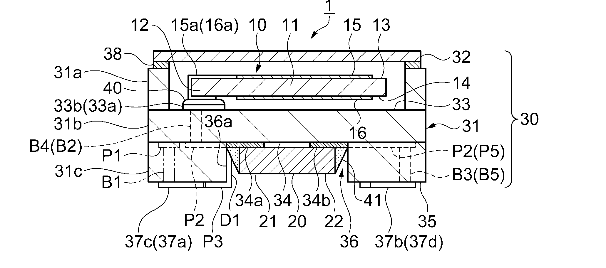
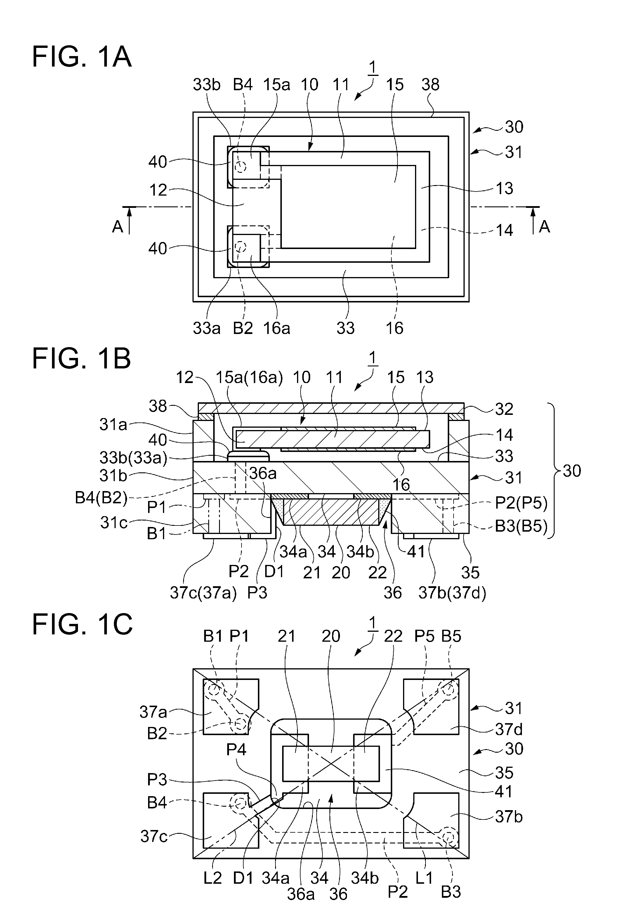
[0076]FIGS. 1A to 1C are diagrams showing a schematic configuration of a quartz crystal resonator according to a first embodiment. FIG. 1A is a plan view when viewed from a lid side, FIG. 1B is a cross-sectional view taken along line A-A of FIG. 1A, and FIG. 1C is a plan view when viewed from a bottom side. Meanwhile, in FIG. 1A, the lid is not shown. In addition, for better understanding, a dimensional ratio of each component is different from that of the actual one.

[0077]As shown in FIGS. 1A to 1C, a quartz crystal resonator 1 includes a quartz crystal resonator element 10 as a resonator element, a thermistor 20 that functions as a thermosensitive element as an electronic element, and a package 30 that accommodates the quartz crystal resonator element 10 and the thermistor 20.

[0078]The quartz crystal resonator element 10, which is an AT cut type which is cut out at a predetermined angle ...

modification example 1

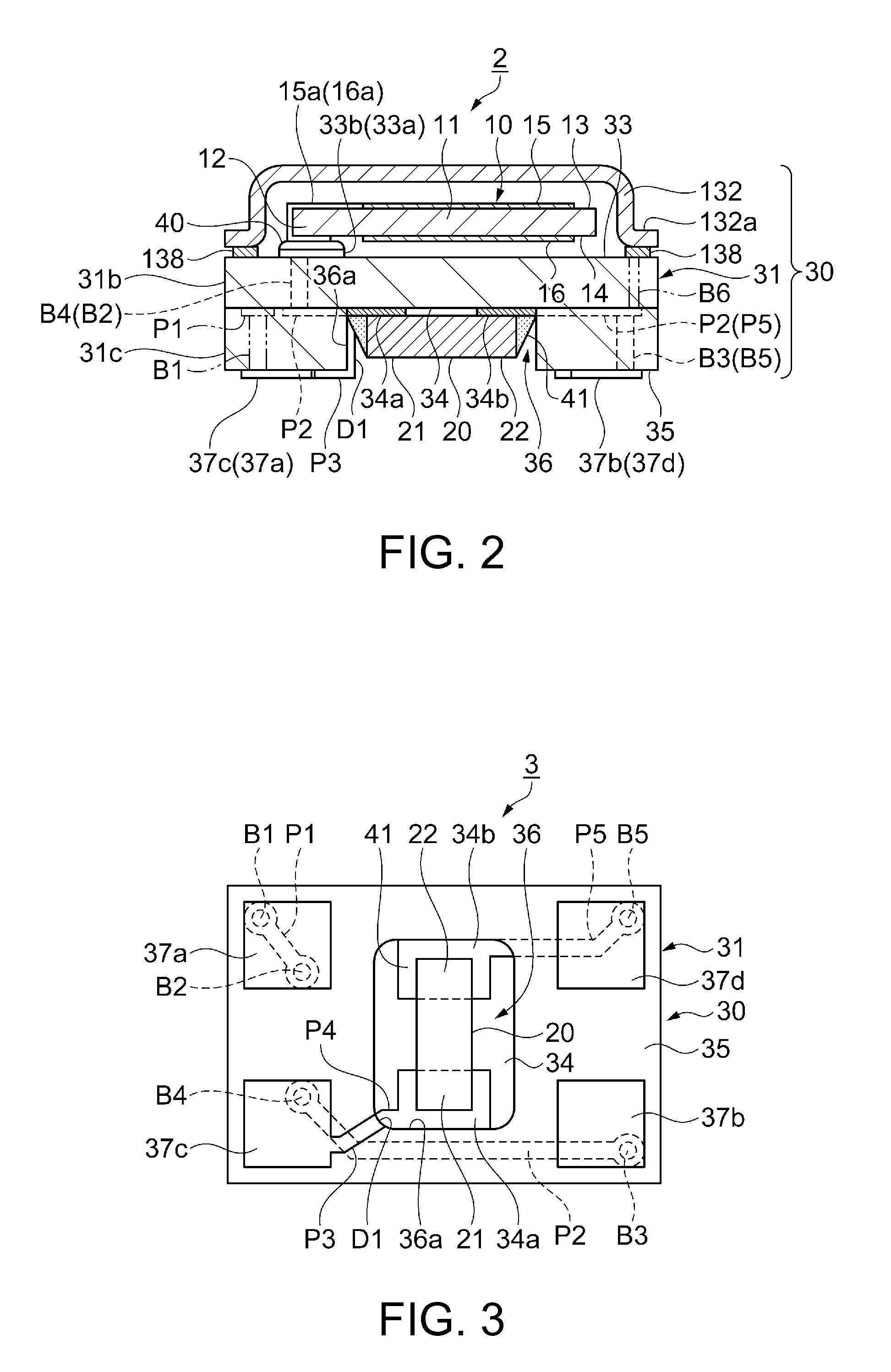
[0150]FIG. 2 is a cross-sectional view showing a schematic configuration of a quartz crystal resonator according to Modification Example 1. Meanwhile, the location of the section is the same as that in FIGS. 1A to 1C.

[0151]Meanwhile, portions in common with those in the first embodiment are denoted by the same reference numerals and signs, and the detailed description thereof will be omitted. The description will be given focusing on the differences from the first embodiment.

[0152]As shown in FIG. 2, a quartz crystal resonator 2 according to Modification Example 1 is different from that according to the first embodiment in the configuration of the package 30.

[0153]In the quartz crystal resonator 2, the frame-shaped first layer 31a of the package base 31 is omitted as compared with the first embodiment.

[0154]In the quartz crystal resonator 2, the first principal surface 33 side of the second layer 31b of the package base 31 is airtightly sealed by a lid 132, made of a metal, which co...

modification example 2

[0166]FIG. 3 is a plan view showing a schematic configuration of a quartz crystal resonator according to Modification Example 2 when viewed from a bottom side.

[0167]Meanwhile, portions in common with those in the first embodiment are denoted by the same reference numerals and signs, and the detailed description thereof will be omitted. The description will be given focusing on the differences from the first embodiment.

[0168]As shown in FIG. 3, a quartz crystal resonator 3 according to Modification Example 2 is different from that according to the first embodiment in an arrangement direction of the thermistor 20.

[0169]The thermistor 20 of the quartz crystal resonator 3 is disposed so that a direction (longitudinal direction) connecting the electrode 21 and the electrode 22 intersects (herein, is orthogonal to) a longitudinal direction (horizontal direction of the paper) of the package base 31.

[0170]Accordingly, the quartz crystal resonator 3 is disposed so that the longitudinal direc...


PUM


Abstract

A quartz crystal resonator includes a quartz crystal resonator element, a thermistor, a second layer including a first principal surface and a second principal surface, and a third layer having a through hole. internal terminals are provided on the first principal surface side, and electrode pads are provided in a portion exposed from the through hole on the second principal surface side. The quartz crystal resonator element is attached to the internal terminals, and the thermistor is attached to the electrode pads. Two mounting terminals are provided on a first diagonal line on the third principal surface side of the third layer, and two mounting terminals are provided on a second diagonal line. At least one of the two electrode pads is connected to any one of the two mounting terminals on the second diagonal line through a first conductive film provided on an inner wall of the through hole.

Description

BACKGROUND[0001]1. Technical Field[0002]The present invention relates to a package, a resonation device, an oscillator including the resonation device, an electronic device, and a moving object.[0003]2. Related Art[0004]Hitherto, as a resonation device, a piezoelectric device has been known which includes a piezoelectric resonation element, a temperature-sensitive component, and a container that has a first accommodation portion accommodating a piezoelectric resonation element and a second accommodation portion accommodating a temperature-sensitive component (for example, see JP-A-2013-102315).[0005]The container of the piezoelectric device includes a first insulating substrate and a second insulating substrate. The first insulating substrate has a through hole constituting the second accommodation portion and includes a plurality of mounting terminals formed in the bottom thereof. The second insulating substrate has a back face being laminated on and fixed to a surface portion of t...

Claims


Application Information

Patent Timeline
IPC IPC(8): H01L41/047H01L41/18H01L41/107
CPCH01L41/047H01L41/18H01L41/107H03H9/1021H03H9/0542H03H9/0552H03H9/10H03H9/172H03B5/32H10N30/88H10N30/872H10N30/875H03H9/08
Inventor KIKUSHIMA, MASAYUKISATO, TOSHIAKI
Owner SEIKO EPSON CORP
Why Eureka
Try Eureka