Composite electronic component, oscillator, electronic apparatus, and mobile object

Inactive Publication Date: 2015-12-31
SEIKO EPSON CORP
View PDF0 Cites 11 Cited by
  • Summary
  • Abstract
  • Description
  • Claims
  • Application Information

AI Technical Summary

Benefits of technology

[0034]According to the configuration, the mobile object having the configuration includes the composite electronic component according to any one of the applicat

Problems solved by technology

As a result, in the composite electronic component, the fixing part between the sensor part and

Method used


Image

  • Composite electronic component, oscillator, electronic apparatus, and mobile object
  • Composite electronic component, oscillator, electronic apparatus, and mobile object
  • Composite electronic component, oscillator, electronic apparatus, and mobile object

Examples


first embodiment

[0046]First, a crystal resonator as an example of a composite electronic component will be explained.

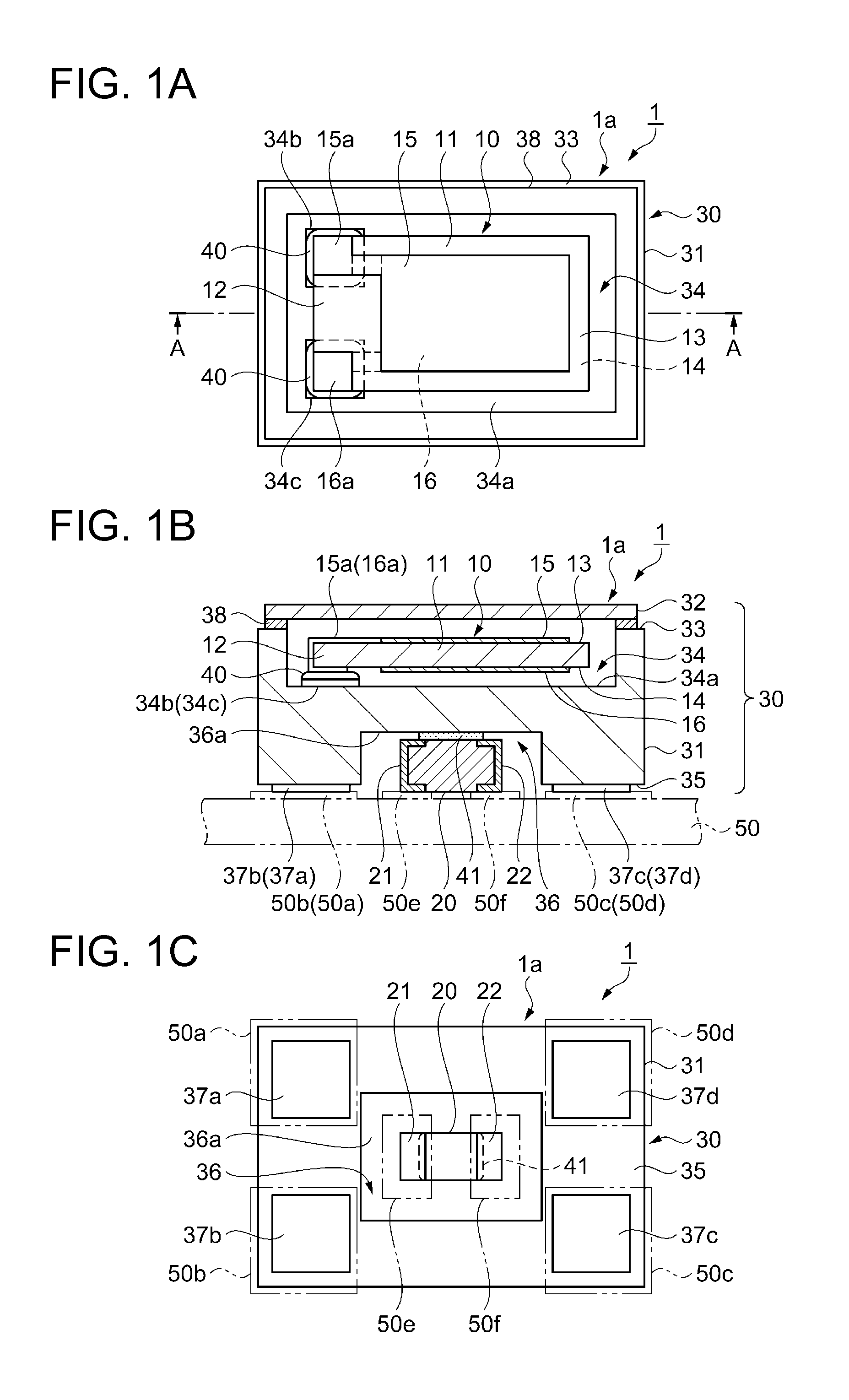
[0047]FIGS. 1A to 1C are schematic diagrams showing an overall configuration of a crystal resonator of the first embodiment. FIG. 1A is a plan view as seen from a lid side, FIG. 1B is a sectional view along line A-A in FIG. 1A, and FIG. 1C is a plan view as seen from a bottom surface side. Note that, in the following plan views as seen from the lid side including FIG. 1A, the lid is omitted. Further, to facilitate understanding, dimension ratios among respective component elements are different from reality.

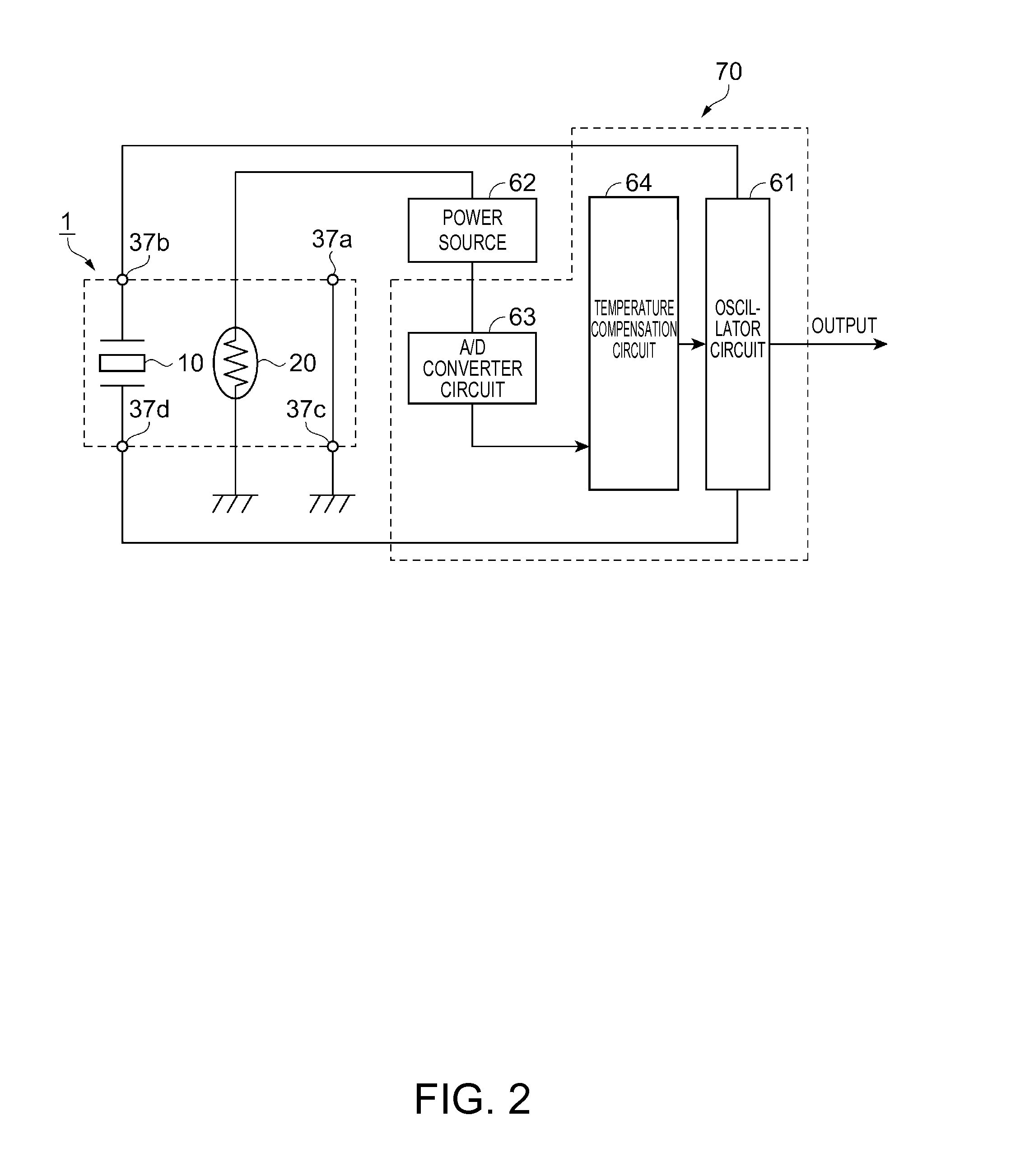
[0048]FIG. 2 is a circuit diagram relating to driving of the crystal resonator containing a thermo-sensitive device housed in the crystal resonator of the first embodiment.

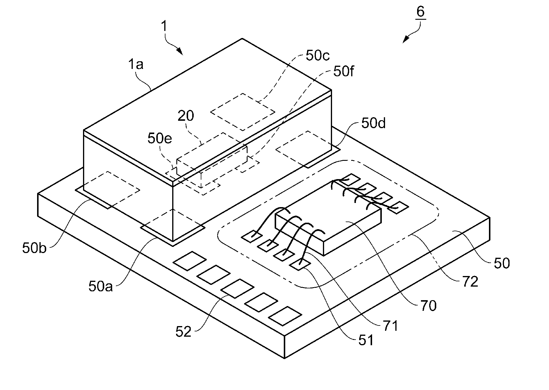
[0049]As shown in FIGS. 1A to 1C, a crystal resonator 1 includes a thermistor 20 as an example of a thermo-sensitive device as a sensor part, and a crystal resonator body 1a as an electronic part having a packag...

modified example 1

[0101]Next, modified example 1 of the first embodiment will be explained.

[0102]FIGS. 3A to 3C are schematic diagrams showing an overall configuration of a quartz crystal resonator of modified example 1 of the first embodiment. FIG. 3A is a plan view as seen from a lid side, FIG. 3B is a sectional view along line A-A in FIG. 3A, and FIG. 3C is a plan view as seen from a bottom surface side.

[0103]Note that the same signs are assigned to the parts in common with the first embodiment and the detailed explanation will be omitted, and the parts different from the first embodiments will be centered for explanation.

[0104]As shown in FIGS. 3A to 3C, a quartz crystal resonator 2 of modified example 1 is different from the first embodiment in the placement orientation of the thermistor 20.

[0105]In the quartz crystal resonator 2, the thermistor 20 is placed so that the longitudinal direction connecting the electrode 21 and the electrode 22 of the thermistor 20 may be along a direction intersect...

modified example 2

[0107]Next, modified example 2 of the first embodiment will be explained.

[0108]FIGS. 4A to 4C are schematic diagrams showing an overall configuration of a quartz crystal resonator of modified example 2 of the first embodiment. FIG. 4A is a plan view as seen from a lid side, FIG. 4B is a sectional view along line A-A in FIG. 4A, and FIG. 4C is a plan view as seen from a bottom surface side.

[0109]Note that the same signs are assigned to the parts in common with the first embodiment and the detailed explanation will be omitted, and the parts different from the first embodiments will be centered for explanation.

[0110]As shown in FIGS. 4A to 4C, a quartz crystal resonator 3 of modified example 2 is different from the first embodiment in the number of electrode terminals.

[0111]In the quartz crystal resonator 3, the electrode terminals 37a, 37c of a quartz crystal resonator body 3a are eliminated and the electrode terminals 37b, 37d extend to the sides where the electrode terminals 37a, 37...


PUM


Abstract

A quartz crystal resonator includes a thermistor having electrodes and a quartz crystal resonator body having a package. The quartz crystal resonator body has a plurality of electrode terminals on a second principal surface of the package and the thermistor is placed at the second principal surface side of the package between the electrode terminals in a plan view or within a range surrounded by the electrode terminals. Both the electrode terminals of the quartz crystal resonator body and the electrodes of the thermistor are mounted on a substrate.

Description

BACKGROUND[0001]1. Technical Field[0002]The present invention relates to a composite electronic component, and an oscillator, an electronic apparatus, and a mobile object including the composite electronic component.[0003]2. Related Art[0004]In related art, as a composite electronic component including a plurality of parts, a composite electronic component including an electronic part and a sensor part fixed to the electronic part and having terminals, and mounted on a substrate by external terminals formed on an outer peripheral surface of a package of the electronic part and the terminals of the sensor part is known (e.g. Patent Document 1 (JP-A-2013-131961)).[0005]In the composite electronic component, the terminals of the sensor part also serve as part of mounting terminals and the planar size may be made smaller compared to the case where the terminals of the sensor part and the mounting terminals are separately provided.[0006]However, in the composite electronic component as o...

Claims


Application Information

Patent Timeline
IPC IPC(8): H03L1/02H03B5/32H03H9/215
CPCH03B5/04H03H9/0547H03H9/08H03H9/1014H03L1/028H03B5/32H03L1/04
Inventor SUZUKI, TAKUMIHANZAWA, MASANORI
Owner SEIKO EPSON CORP
Why Eureka
Try Eureka