
Temperature compensated piezoelectric oscillator and electronic apparatus comprising it

a piezoelectric oscillator and temperature compensation technology, applied in the field of piezoelectric oscillators, can solve the problem that the resonant frequency of piezoelectric elements cannot be compensated in the range of sufficient temperature, and achieve the effect of simple structur

Active Publication Date: 2007-04-17
MURATA MFG CO LTD
View PDF8 Cites 12 Cited by
  • Summary
  • Abstract
  • Description
  • Claims
  • Application Information

AI Technical Summary

Benefits of technology

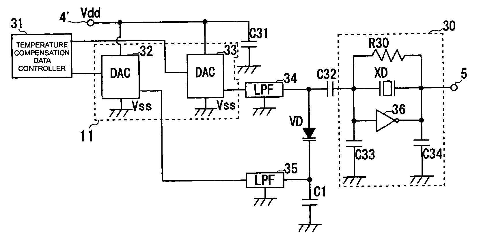
The present invention provides a temperature-compensated piezoelectric oscillator that ensures temperature compensation and outputs a high-frequency signal with a stable resonant frequency even when the power supply voltage is reduced. The temperature compensation is achieved by applying a voltage to the variable capacitance element that changes in opposite directions based on the ambient temperature. The circuit includes a compensation voltage generation circuit that generates a first and second voltage to the variable capacitance element, with the second voltage being the difference between the first and second voltage. The compensation voltage generation circuit includes a thermo-sensitive element and resistance elements. The temperature compensation data is generated based on the detected ambient temperature and converted into a digital format for application to the variable capacitance element. The temperature-compensated piezoelectric oscillator ensures stable operation at low power supply voltages and is suitable for use in electronic apparatuses.

Problems solved by technology

Accordingly, a sufficient temperature compensation for the resonant frequency of the piezoelectric element may not be achieved in the range of the voltage generated from the temperature compensation voltage generation circuit.

Method used


Image

  • Temperature compensated piezoelectric oscillator and electronic apparatus comprising it
  • Temperature compensated piezoelectric oscillator and electronic apparatus comprising it
  • Temperature compensated piezoelectric oscillator and electronic apparatus comprising it

Examples


Embodiment Construction

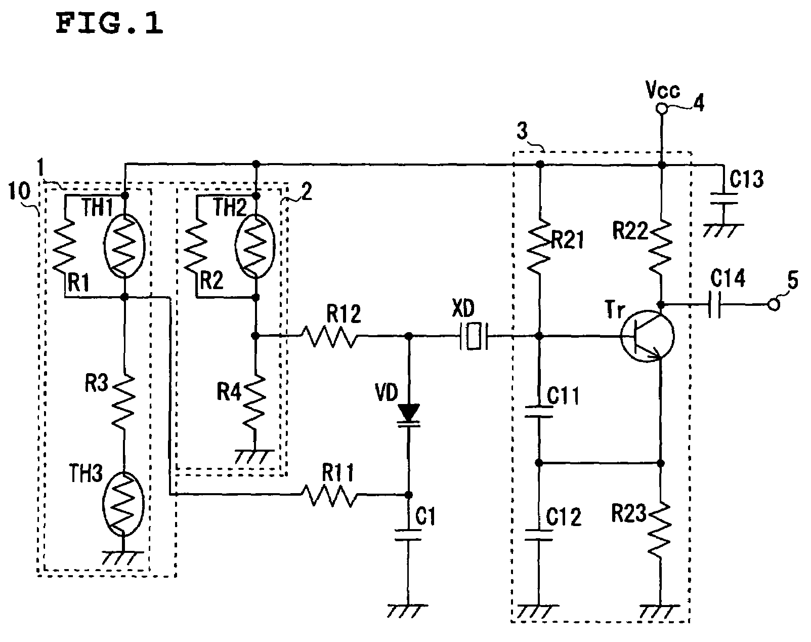
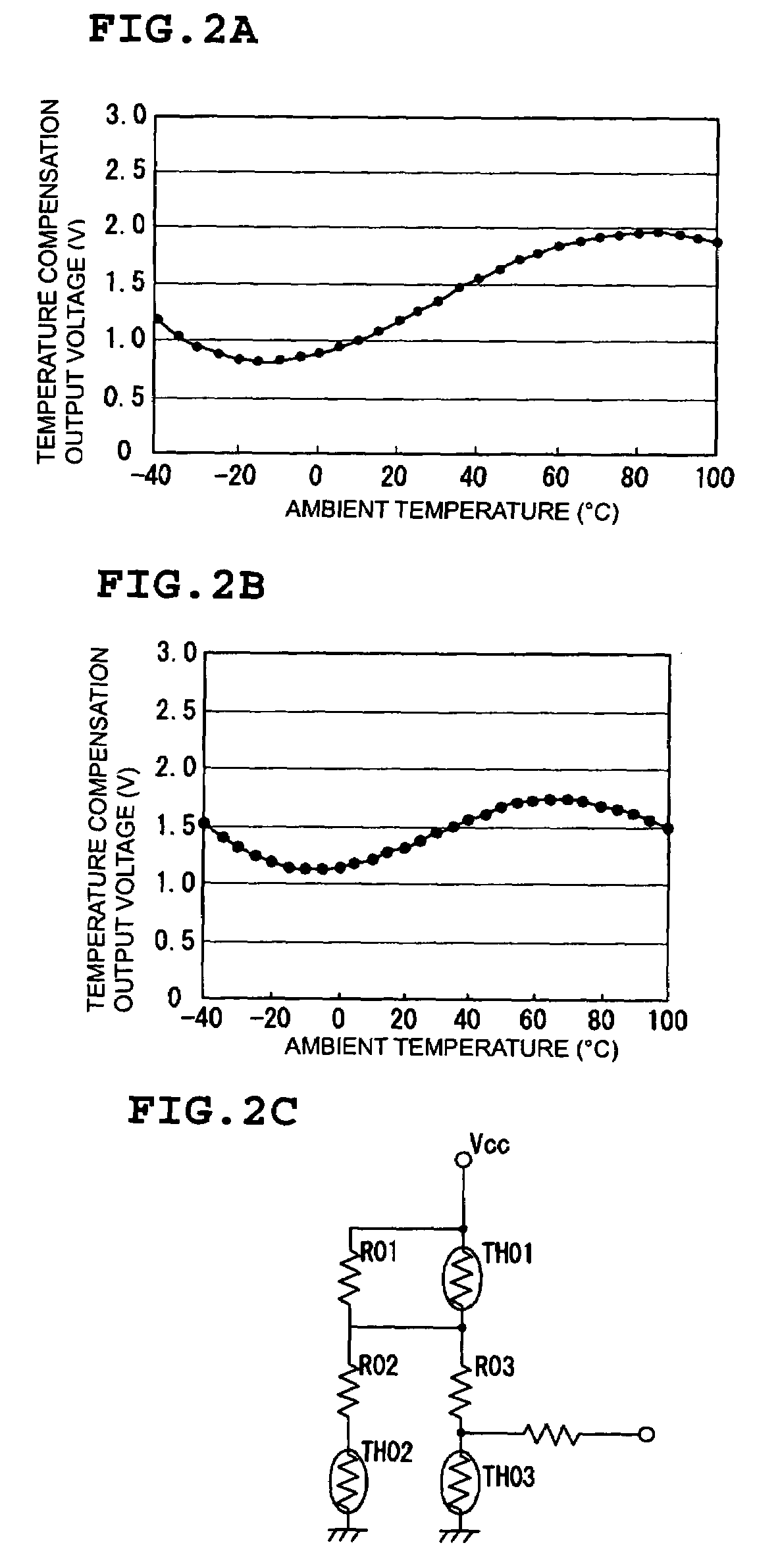
[0038]A temperature-compensated piezoelectric oscillator according to a first preferred embodiment of the present invention will be described with reference to FIGS. 1 and 2.

[0039]FIG. 1 is an equivalent circuit diagram of the temperature-compensated piezoelectric oscillator according to the present preferred embodiment.

[0040]As shown in FIG. 1, the temperature-compensated piezoelectric oscillator preferably includes an AT-cut quartz crystal resonator (hereinafter, simply referred to as a “quartz crystal resonator”) XD, which is a piezoelectric element, an amplifying circuit 3 connected to one end of the quartz crystal resonator XD, a varactor diode VD, which is a variable capacitance element, connected the other end of the quartz crystal resonator XD, and a temperature compensation voltage generation circuit 10. Two outputs from the temperature compensation voltage generation circuit 10 are connected to ends of the varactor diode VD via resistors R11 and R12, respectively.

[0041]The...


PUM


Abstract

A temperature-compensated piezoelectric oscillator includes an AT-cut quartz crystal resonator, an amplifying circuit connected to one end of the quartz crystal resonator, a varactor diode connected to the other end of the quartz crystal resonator, and a temperature compensation voltage generation circuit connected to ends of the varactor diode via resistors. The temperature compensation voltage generation circuit includes a first voltage generation circuit that includes thermistors and resistors and that is connected to the cathode of the varactor diode, and a second voltage generation circuit that includes a thermistor and resistors and that is connected to the anode of the varactor diode (VD).

Description

BACKGROUND OF THE INVENTION[0001]1. Field of the Invention[0002]The present invention relates to piezoelectric oscillators, and more particularly, to a temperature-compensated piezoelectric oscillator that compensates for an oscillation frequency in accordance with an ambient temperature and also relates to an electronic apparatus including the temperature-compensated piezoelectric oscillator.[0003]2. Description of the Related Art[0004]In general, piezoelectric oscillators include a piezoelectric element, such as a crystal strip, that resonates at a predetermined frequency in accordance with an applied voltage and an amplifying circuit for amplifying a resonant signal by the piezoelectric element and for outputting the amplified resonant signal. The resonant frequency of the piezoelectric element, such as a crystal strip, is dependent upon the temperature. Thus, even if the same voltage is applied, the resonant frequency is changed as the temperature of the element changes.[0005]In...

Claims


Application Information

Patent Timeline
Patent Type & Authority Patents(United States)
IPC IPC(8): H03B5/32H03B5/04H03B5/36
CPCH03B5/04H03B5/368H03L1/028
Inventor KATO, AKIRA
Owner MURATA MFG CO LTD
Learn More