Electronic component

a technology of electronic components and components, applied in the field of electronic components, can solve the problem of not obtaining a sufficient attenuation in a band other than the pass band of the low-pass filter, and achieve the effect of reducing insertion loss and sufficient attenuation

Active Publication Date: 2015-04-30
MURATA MFG CO LTD
View PDF5 Cites 5 Cited by
  • Summary
  • Abstract
  • Description
  • Claims
  • Application Information

AI Technical Summary

Benefits of technology

[0009]According to a preferred embodiment of the present invention, it is possible to obtain a sufficient attenuation in a band other than a pass band while insertion loss is being reduced.

Problems solved by technology

Accordingly, in a low pass filter, the possibility that a high frequency signal is transmitted between three-dimensional spiral inductors is increased, thus failing to obtain a sufficient attenuation in a band other than a pass band of the low pass filter.

Method used


Image

  • Electronic component
  • Electronic component
  • Electronic component

Examples


first modified example

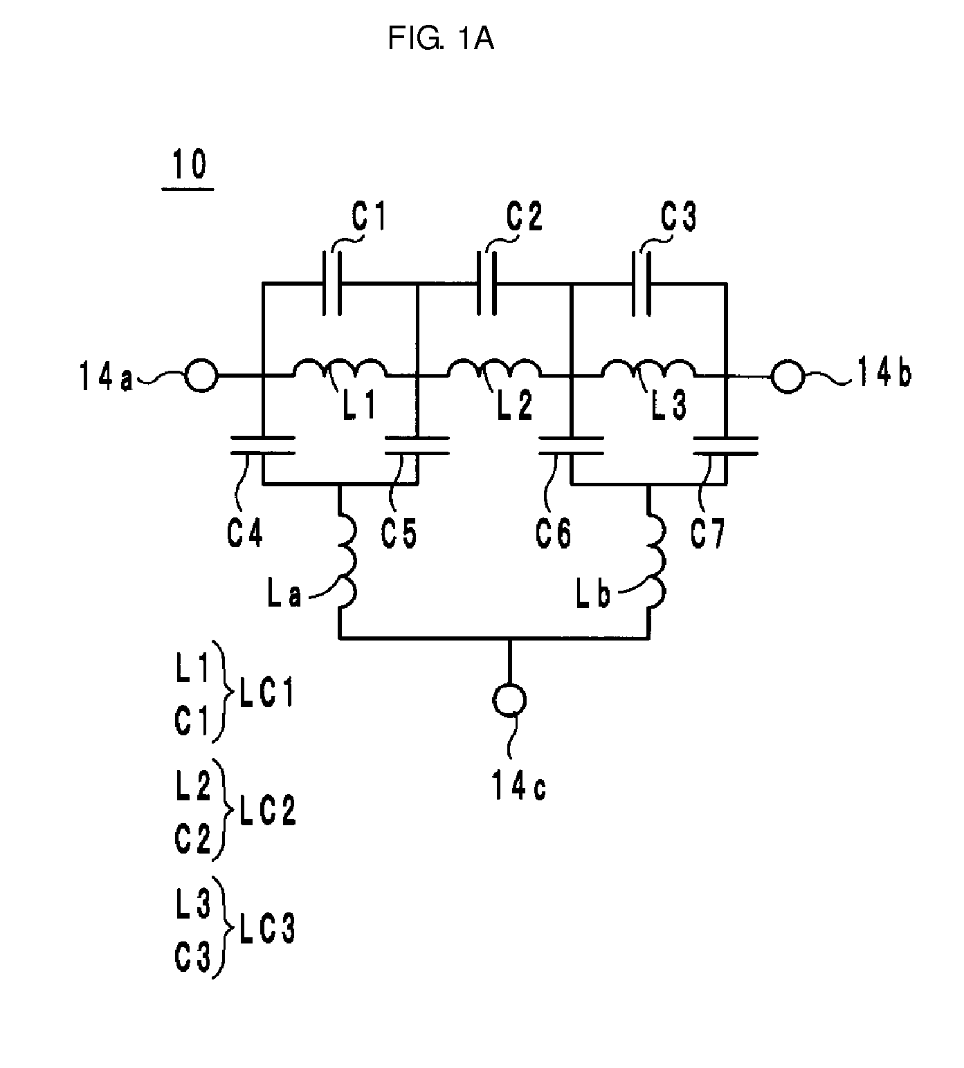
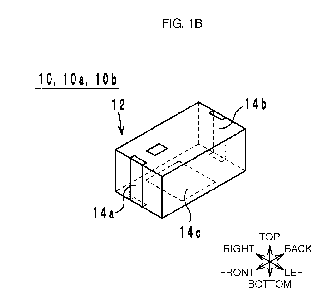
[0107]The configuration of a filter according to a first modified example of a preferred embodiment of the present invention will be described below with reference to FIGS. 4 and 5. FIG. 4 is an equivalent circuit diagram of an electronic component 10a according to the first modified example. FIG. 5 is an exploded perspective view of a multilayer body 12 of the electronic component 10a according to the first modified example. The exploded perspective view of FIG. 5 corresponds to that of FIG. 2B showing the multilayer body 12 of the electronic component 10. The other exploded perspective views of the electronic component 10a are the same as those of the electronic component 10 (FIGS. 2A, 2C, and 2D).

[0108]The electronic component 10a is different from the electronic component 10 in that it includes a capacitor C8. The electronic component 10a will be described below by mainly referring to this different point.

[0109]The capacitor C8 is connected between the external terminals 14a and...

second modified example

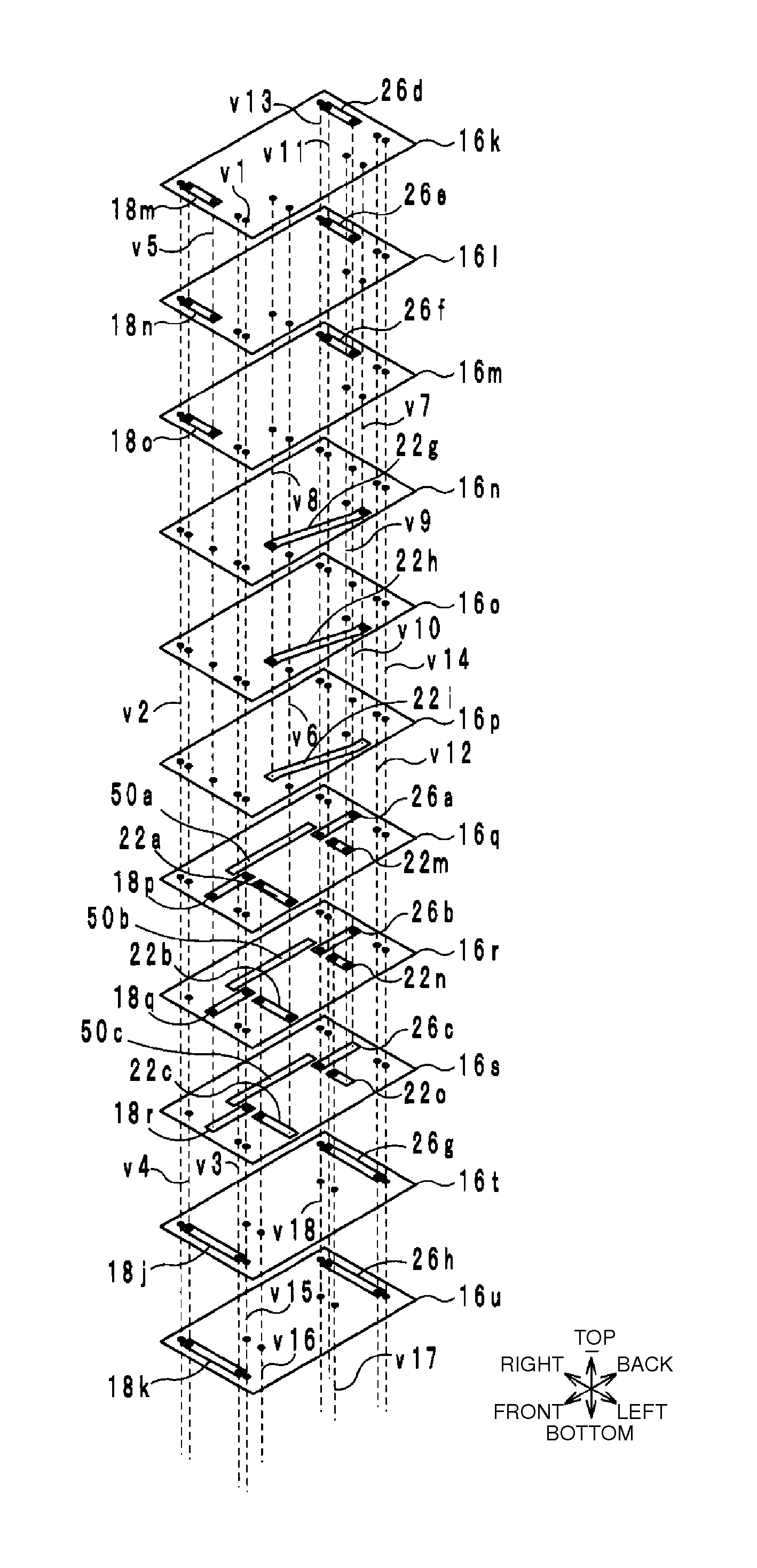
[0114]The configuration of a filter according to a second modified example of a preferred embodiment of the present invention will be described below with reference to FIG. 6. FIG. 6 is an exploded perspective view of a multilayer body 12 of an electronic component 10b according to the second modified example. The exploded perspective view of FIG. 6 corresponds to that of FIG. 2A showing the multilayer body 12 of the electronic component 10. The other exploded perspective views of the electronic component 10b are the same as those of the electronic component 10 (FIGS. 2B through 2D). The equivalent circuit diagram of the electronic component 10b is the same as that of the electronic component 10a, and thus, FIG. 4 will be used for describing the electronic component 10b.

[0115]The electronic component 10b, as well as the electronic component 10a, is different from the electronic component 10 in that it includes a capacitor C8. The electronic component 10b will be described below by ...


PUM


Abstract

In an electronic component, first through n-th LC parallel resonators respectively include first through n-th inductors disposed in a device body such that they are sequentially arranged in a first direction in an order from the first inductor to the n-th inductor. The first and the n-th inductors are wound around respective winding axes extending along the first direction. At least one predetermined inductor among the second through the (n−1)-th inductors is wound around a winding axis extending in a second direction which is perpendicular or substantially perpendicular to the first direction. A center of the predetermined inductor in the second direction is positioned toward one side of the second direction with respect to the winding axes of the first and the n-th inductors, as viewed from a plane of the device body in a third direction which is perpendicular or substantially perpendicular to the first and second directions.

Description

BACKGROUND OF THE INVENTION[0001]1. Field of the Invention[0002]The present invention relates to an electronic component, and more particularly, to an electronic component including three or more LC parallel resonators.[0003]2. Description of the Related Art[0004]As a typical example of electronic components of the related art, a three-dimensional spiral inductor disclosed in Japanese Unexamined Patent Application Publication No. 2006-190934 (FIG. 16a) is known. This three-dimensional spiral inductor is a helical coil which is disposed within a multilayer body and which turns around a winding axis extending in a direction substantially orthogonal to a stacking direction of the multilayer body. Such a three-dimensional spiral inductor is used in, for example, a low pass filter.[0005]A low pass filter using three-dimensional spiral inductors is formed by connecting a plurality of LC parallel resonators, each being constituted by a three-dimensional spiral inductor and a capacitor, in ...

Claims


Application Information

Patent Timeline
Patent Type & Authority Applications(United States)
IPC IPC(8): H03H7/01
CPCH03H7/1766H03H7/0115H03H2001/0085H03H7/1708H03H7/1725
Inventor MASUDA, HIROSHI
Owner MURATA MFG CO LTD
Why Eureka
Try Eureka