Imaging lens and imaging apparatus

Active Publication Date: 2015-04-30
FUJIFILM CORP
View PDF1 Cites 4 Cited by
  • Summary
  • Abstract
  • Description
  • Claims
  • Application Information

AI Technical Summary

Benefits of technology

[0027]The imaging apparatus of the present invention includes the imaging lens of the present invention. Therefore,

Problems solved by technology

However, all of the lenses proposed in Patent Documents 1 through 3 have d

Method used


Image

  • Imaging lens and imaging apparatus
  • Imaging lens and imaging apparatus
  • Imaging lens and imaging apparatus

Examples


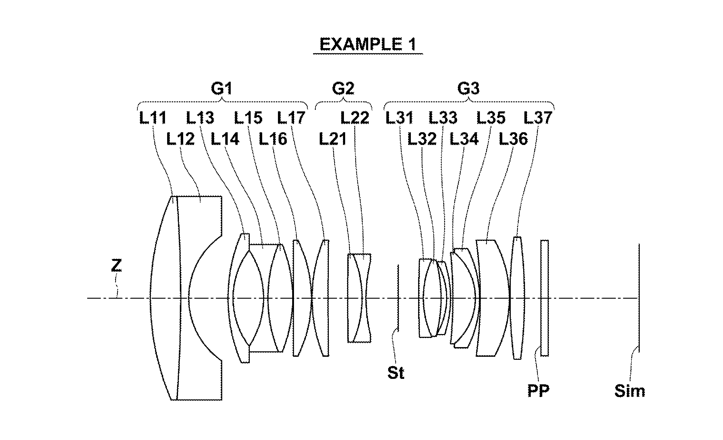
Embodiment Construction

);

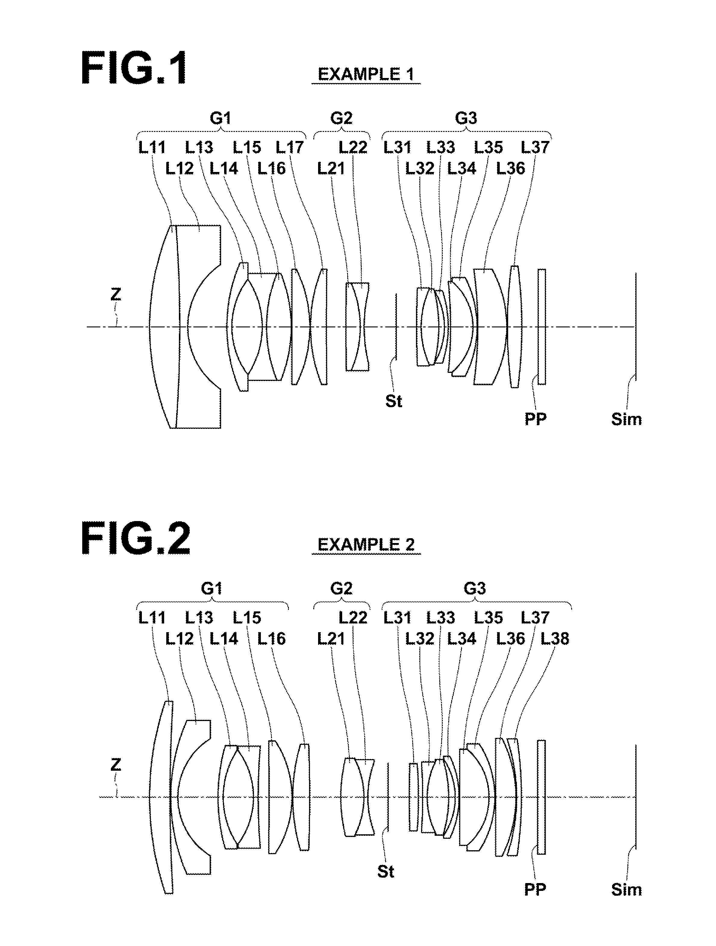
[0029]FIG. 2 is a cross section illustrating the lens structure of an imaging lens in Example 2 of the present invention;

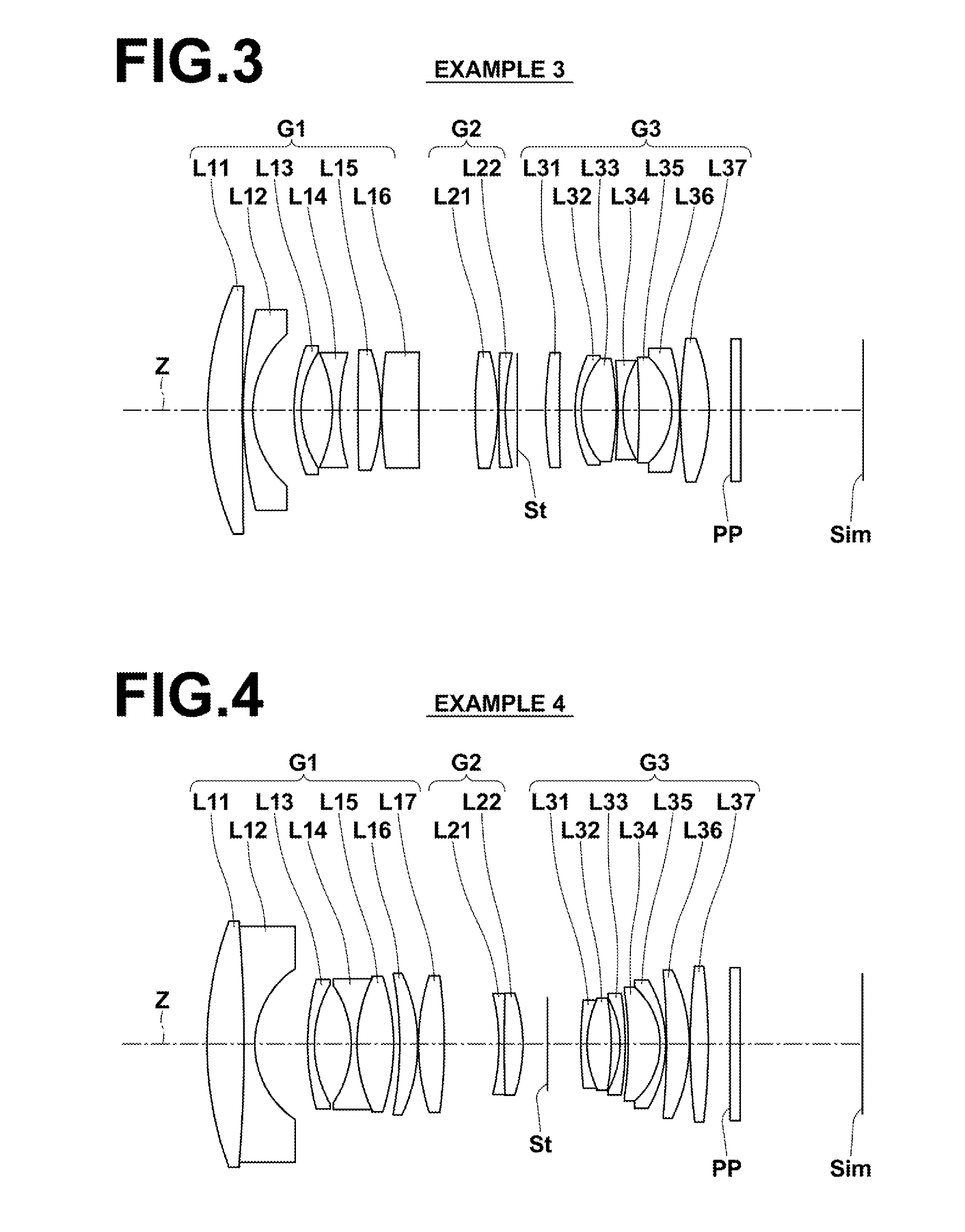
[0030]FIG. 3 is a cross section illustrating the lens structure of an imaging lens in Example 3 of the present invention;

[0031]FIG. 4 is a cross section illustrating the lens structure of an imaging lens in Example 4 of the present invention;

[0032]FIG. 5 is a cross section illustrating the lens structure of an imaging lens in Example 5 of the present invention;

[0033]FIG. 6 is a cross section illustrating the lens structure of an imaging lens in Example 6 of the present invention;

[0034]FIG. 7 is aberration diagrams (Sections A through E) of the imaging lens in Example 1 of the present invention;

[0035]FIG. 8 is aberration diagrams (Sections A through E) of the imaging lens in Example 2 of the present invention;

[0036]FIG. 9 is aberration diagrams (Sections A through E) of the imaging lens in Example 3 of the present invention;

[0037]FIG. 10 is aberration diagrams (S...


PUM


Abstract

An imaging lens consists of a first lens group, a second lens group, an aperture stop and a third lens group that has positive refractive power in this order from an object side. The first lens group consists of an L11 lens having positive refractive power, an L12 lens having negative refractive power, an L13 meniscus lens having negative refractive power with its concave surface facing an image side, an L14 lens having negative refractive power with its concave surface facing the object side and two or three lenses, each having positive refractive power, in this order from the object side. The second lens group consists of an L2p lens having positive refractive power and an L2n lens having negative refractive power.

Description

CROSS-REFERENCE TO RELATED APPLICATIONS[0001]This application is a Continuation of PCT International Application No. PCT / JP2013 / 003926 filed on Jun. 24, 2013, which claims priority under 35 U.S.C. §119(a) to Japanese Patent Application No. 2012-151319 filed on Jul. 5, 2012. Each of the above applications are hereby expressly incorporated by reference, in its entirety, into the present application.BACKGROUND OF THE INVENTION[0002]1. Field of the Invention[0003]The present invention relates to a retrofocus-type imaging lens and an imaging apparatus. In particular, the present invention relates to an imaging lens used in electronic cameras, such as a digital camera, a camera for broadcasting, a camera for surveillance and a camera for film making, and an imaging apparatus including the imaging lens.[0004]2. Description of the Related Art[0005]As an imaging lens used in an imaging apparatus, such as a video camera and an electronic still camera, which uses an imaging device, such as a C...

Claims


Application Information

Patent Timeline
IPC IPC(8): G02B13/04G02B9/64
CPCG02B9/64G02B13/04G02B13/0015
Inventor YAMADA, HIROSHICHO, MICHIO
Owner FUJIFILM CORP
Why Eureka
Try Eureka