Memory cell comprising non-self-aligned horizontal and vertical control gates

a technology of control gate and memory cell, which is applied in the direction of digital storage, instruments, semiconductor devices, etc., can solve the problems of inability to apply different voltages, inability to control the electrical characteristics of the memory cell by manufacturing methods, and disadvantages of occupying more semiconductor surfaces of split-gate memory cells

Active Publication Date: 2015-04-30
STMICROELECTRONICS (ROUSSET) SAS
View PDF4 Cites 8 Cited by
  • Summary
  • Abstract
  • Description
  • Claims
  • Application Information

AI Technical Summary

Benefits of technology

[0022]Some embodiments of the present disclosure also relate to a memory circuit comprising a memory cell according to the present disclosure and means for erasing the memory cell by tunnel effect configured to apply electric potentials to the vertical selection gate and the horizonta

Problems solved by technology

Offsetting their good injection performance, split gate memory cells have the disadvantage of occupying more semiconductor surface than conventional flash memory cells, also programmed by hot-electron injection but comprising only one control gate.
Furthermore, as the control CG and selection SG gates have the same electric potential as they are formed by the same polysilicon layer (26), it is not possible to apply

Method used


Image

  • Memory cell comprising non-self-aligned horizontal and vertical control gates
  • Memory cell comprising non-self-aligned horizontal and vertical control gates
  • Memory cell comprising non-self-aligned horizontal and vertical control gates

Examples


Embodiment Construction

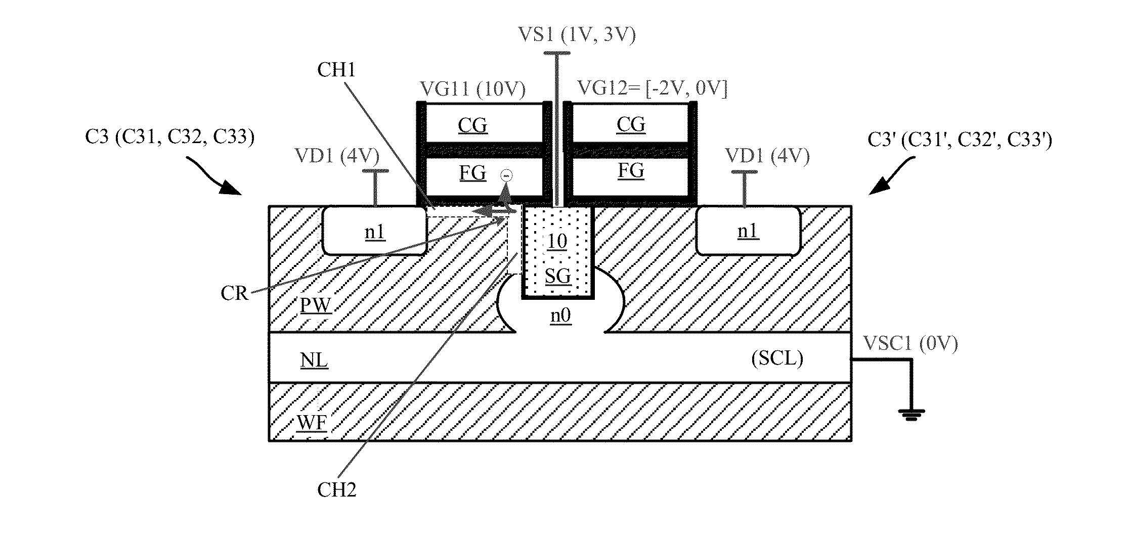
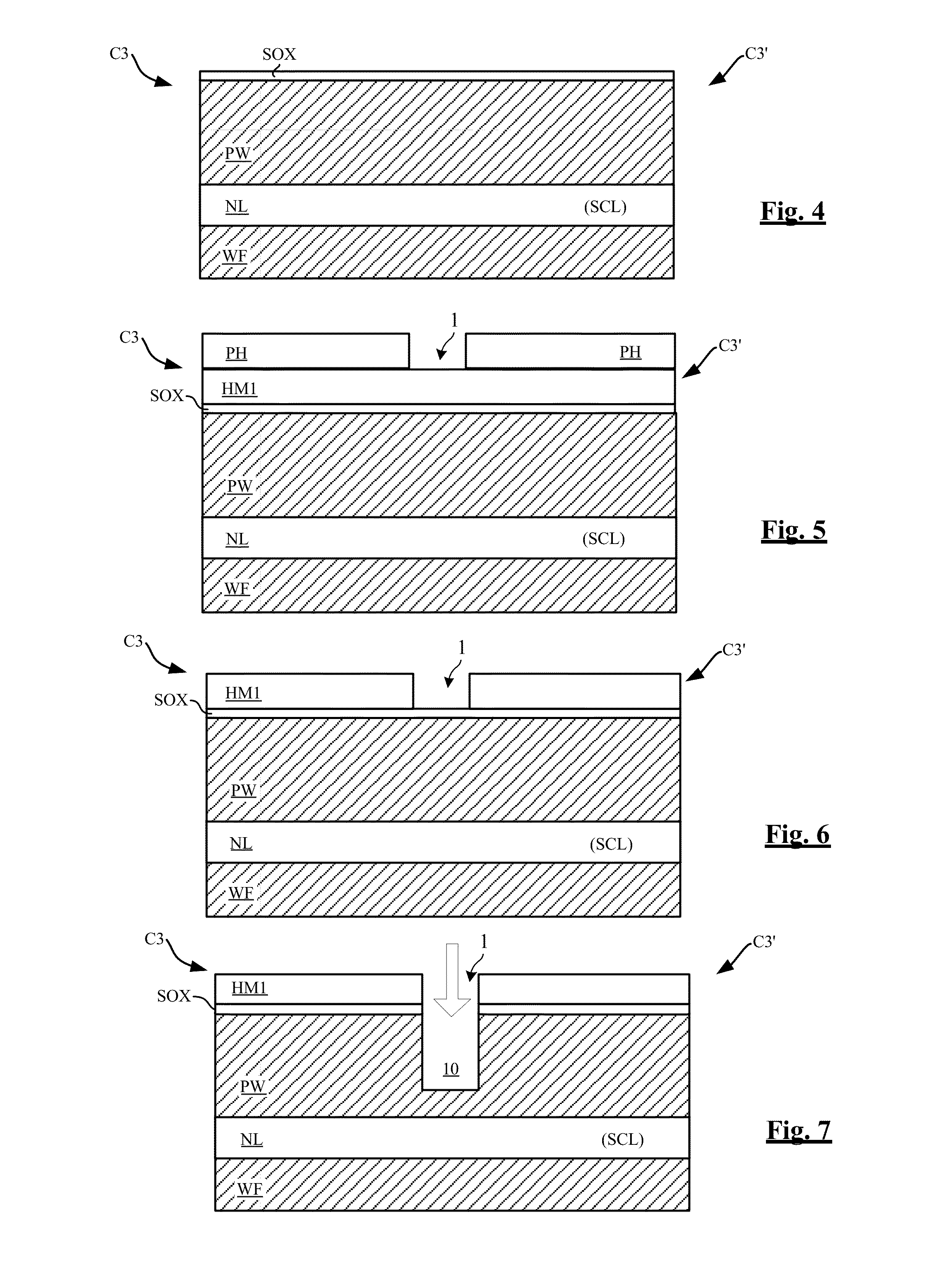
[0043]FIGS. 4 to 18 are cross-sections showing steps of a method of manufacturing a memory cell according to the present disclosure. FIGS. 13A and 13B show two alternatives of a step of this method. FIGS. 14A to 14C and 15A to 15C show three alternatives of two other steps of this method. FIGS. 19A to 19C show the three alternatives C31, C32, C33 of a memory cell C3 according to the present disclosure produced with this method and its alternatives.

[0044]The memory cell C3 (C31, C32, C33) shown in FIGS. 19A, 19B, 19C comprises a floating gate FG formed on a substrate PW, a horizontal control gate CG extending over the floating gate FG, and a selection gate SG formed in a trench 10 made in the substrate, the trench being covered with a dielectric layer D1. The memory cell C3 is here produced at the same time as a twin memory cell C3′ (C31′, C32′, C33′) using the same selection gate SG.

[0045]According to the present disclosure, the floating gate FG extends above a portion of the select...


PUM


Abstract

The present disclosure relates to a memory cell comprising a vertical selection gate extending in a trench made in a substrate, a floating gate extending above the substrate, and a horizontal control gate extending above the floating gate, wherein the floating gate also extends above a portion of the vertical selection gate over a non-zero overlap distance. Application mainly to the production of a split gate memory cell programmable by hot-electron injection.

Description

BACKGROUND[0001]1. Technical Field[0002]The present disclosure relates to split gate memory cells each comprising a selection transistor section and a floating-gate transistor section. The selection transistor section comprises a selection gate and the floating-gate transistor section comprises a floating gate and a control gate.[0003]2. Description of the Related Art[0004]So-called “split gate” memory cells are conventionally programmed by hot-electron injection (or “hot-carrier injection”). Compared to tunnel-effect programming, programming by hot electrons has the advantage of being short, generally 100 times shorter than tunnel-effect programming. The programming time of a memory cell by hot-electron injection is typically in the order of a few microseconds compared to a few milliseconds for tunnel-effect programming.[0005]During hot-electron programming, the two transistor sections of the memory cell cooperate in order to inject electric charges into the floating gate. The sele...

Claims


Application Information

Patent Timeline
IPC IPC(8): H01L27/115H01L21/3205H01L29/788H01L29/423H01L29/66H01L29/78G11C16/14H01L21/3213
CPCH01L27/11524G11C16/14H01L21/32051H01L21/32133H01L29/7883H01L29/66825H01L29/66666H01L29/7827H01L29/42328H01L29/42336H01L29/7881H01L29/7885G11C16/0425H01L29/40114H10B41/30H10B41/35H01L21/30604H01L29/788
Inventor LA ROSA, FRANCESCONIEL, STEPHANDELALLEAU, JULIENREGNIER, ARNAUD
Owner STMICROELECTRONICS (ROUSSET) SAS
Why Eureka
Try Eureka