Garment
a technology of garments and protective garments, applied in the field of garments, can solve the problems of reducing productivity, user may feel oppression, sensor electrodes are easily deteriorated, etc., and achieve the effects of reducing costs, suppressing product life reduction, and improving productivity
- Summary
- Abstract
- Description
- Claims
- Application Information
AI Technical Summary
Benefits of technology
Problems solved by technology
Method used
Image

Examples
first embodiment
[0051]Next, a first embodiment of the present invention will be explained with reference to the drawings.
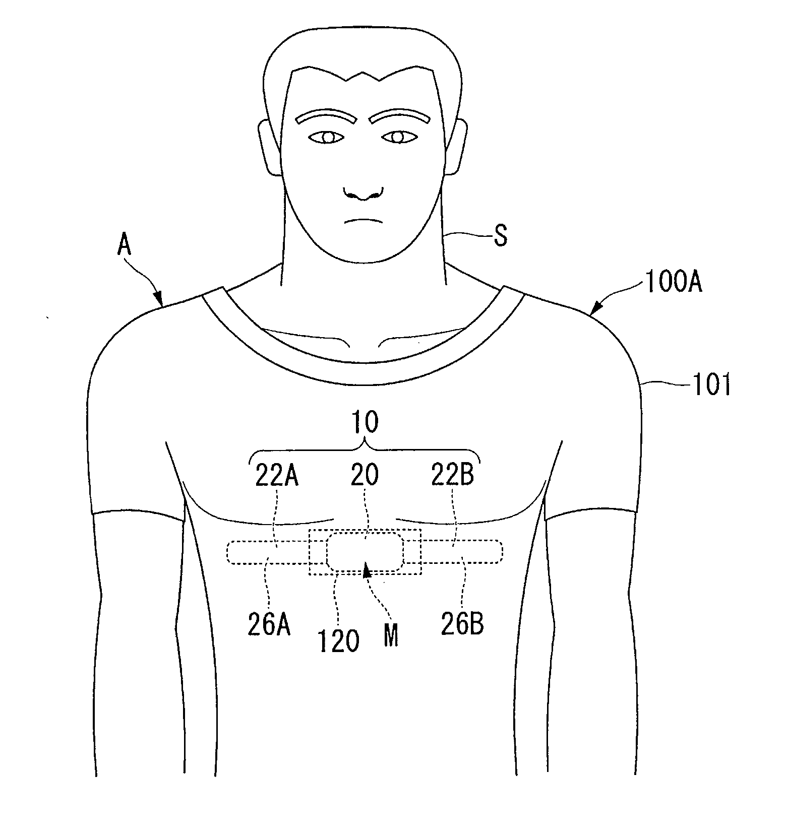
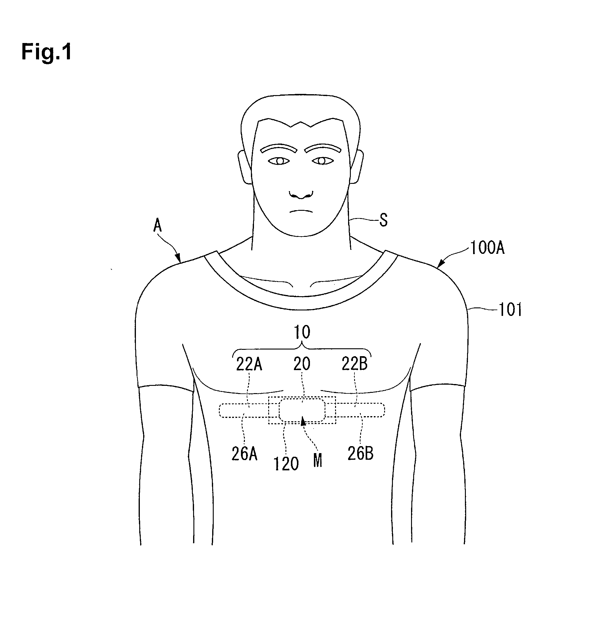
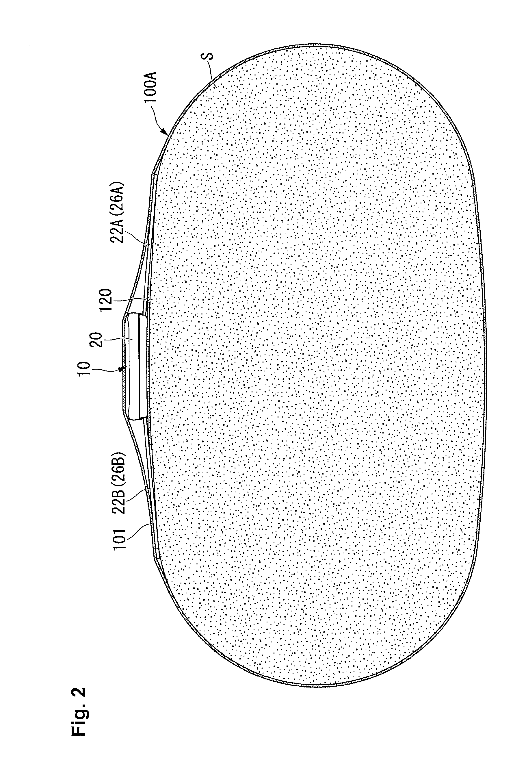
[0052]FIG. 1 is a front view showing a state where a garment according to the present invention is worn by a user, FIG. 2 is a transverse sectional view showing a state where the garment is worn by the user and FIG. 3 is a perspective view of a heart rate measuring device.
[0053]As shown in FIG. 1, a heart rate measuring device (corresponding to a “biological information detecting device” in claims) 10 closely contacts a chest of a user S as a biological surface by being attached to a garment 100A to be worn by the user to thereby detect an electrocardiographic signal generated by heartbeats, and transmits the detected electrocardiographic signal by wireless communication.
[0054]As shown in FIG. 2, the heart rate measuring device 10 includes a device body 20 and a pair of heart rate detecting portions 22A and 22B integrally formed on both sides of the device body 20.
[0055]As shown ...
second embodiment
[0083]FIG. 6 is a perspective view showing a state before the heart rate measuring device is held in the device housing portion of the garment according to a second embodiment of the present invention. FIG. 7 is a perspective view showing a state where the heart rate measuring device is held in the device housing portion of the garment shown in FIG. 6.
[0084]As shown in FIG. 6 and FIG. 7, a garment 100B includes the garment body 101 and device housing portions 122 provided in the garment 101 and holding the heart rate measuring device 10 so as to be attached / detached.
[0085]A plurality of (three in the embodiment) device housing portions 122 are arranged along the lengthwise direction L of the garment body 101 to thereby form a housing portion group X.
[0086]Respective device housing potions 122 may be formed by sewing a piece of cloth material to the garment body 101 with a given pitch in the lengthwise direction to thereby set portions between respective sewn portions as respective d...
third embodiment
[0089]FIG. 8 is a perspective view showing a state before the heart rate measuring device is held in device housing portions of a garment according to a third embodiment of the present invention. FIG. 9 is a perspective view showing a state where the heart rate measuring device is held in the device housing portions of the garment of FIG. 8.
[0090]As shown in FIG. 8 and FIG. 9, a garment 100C includes the garment body 101 and device housing portions 123 provided in the garment 101 and holding the heart rate measuring device 10 so as to be attached / detached.
[0091]In the present embodiment, a plurality of device housing portions 123 are arranged along the lengthwise direction L to thereby form a plurality of housing portion groups (a first housing portion group X1 to a third housing portion group X3), which are aligned in the width direction W of the garment body 101. Specifically, in the first housing portion group X1 and the third housing portion group X3 positioned at both sides in ...
PUM
 Abstract
Description
Claims
Application Information
 - R&D
- Intellectual Property
- Life Sciences
- Materials
- Tech Scout
- Unparalleled Data Quality
- Higher Quality Content
- 60% Fewer Hallucinations
Browse by: Latest US Patents, China's latest patents, Technical Efficacy Thesaurus, Application Domain, Technology Topic, Popular Technical Reports.
© 2025 PatSnap. All rights reserved.Legal|Privacy policy|Modern Slavery Act Transparency Statement|Sitemap|About US| Contact US: help@patsnap.com