Laminated iron core manufacturing method and blanking die apparatus

a technology of laminated iron core and blanking die, which is applied in the manufacture of stator/rotor bodies, metal working apparatuses, and applying solid insulation, etc., can solve the problems of increasing the number of replacement parts in maintenance, reducing productivity, and shortening the life of cutting tools and even life, so as to reduce or prevent the shortened life of cutting tools, reduce or eliminate the eccentric load, and reduce or prevent the inclination of the blanking die.

Active Publication Date: 2015-05-07
MITSUI HIGH TEC INC
View PDF2 Cites 4 Cited by
  • Summary
  • Abstract
  • Description
  • Claims
  • Application Information

AI Technical Summary

Benefits of technology

[0025]When the auxiliary cutting tools are operated simultaneously with the operations of the cutting tools of the machining stations, to the blanking die apparatus, there is applied the total blanking load which is the sum of the total core piece forming load and total disposal hole forming load, whereby the load center position of the total blanking load is caused to move with the movement of the load center position of the total disposal hole forming load. Thus, by adjusting the load center position of the total disposal hole forming load, that is, by adjusting the number and position of disposal holes to be formed within the scrap forming area respectively, the load center position of the total blanking load can be made to near or coincide with the center position of the blanking die apparatus. This can realize the further reduction or elimination of the eccentric load generated in the blanking die apparatus, thereby reducing or preventing the inclination of the blanking die apparatus.
[0026]Consequently, variations in the clearances respectively set between the punches and dies to be paired can be reduced or prevented, thereby reducing or preventing the shortened lives of the cutting tools caused by the breakage of the punches and dies and the shortened lives of devices such as the base of a press and a ram belonging to the blanking die apparatus simultaneously. Thus, since the maintenance burden of the blanking die apparatus can be reduced, the cost can be reduced and the productivity can be enhanced.
[0027]In the laminated iron core manufacturing method according to the first aspect of the present invention, in the case that the multiple disposal holes are formed, when the disposal holes are formed with a clearance between them, the total of the outer ...

Problems solved by technology

Such remarkable influence shortens the lives of the cutting tools and also even the lives of the base of a press and a ram belonging to the blanking die apparatus.
This increases the main...

Method used


Image

  • Laminated iron core manufacturing method and blanking die apparatus
  • Laminated iron core manufacturing method and blanking die apparatus
  • Laminated iron core manufacturing method and blanking die apparatus

Examples


Embodiment Construction

[0037]Next, description is given of an embodiment of the present invention with reference to the accompanying drawings for understanding of the present invention.

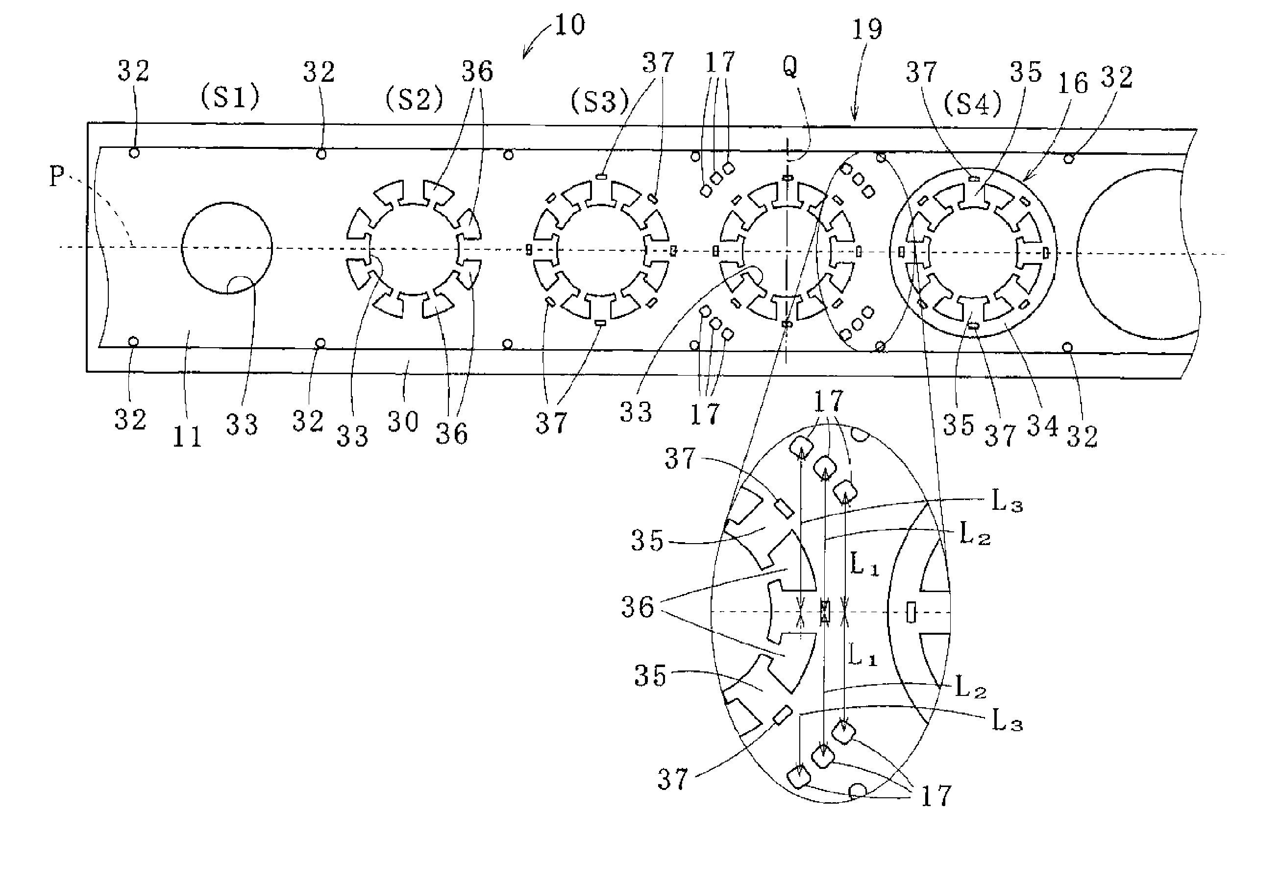
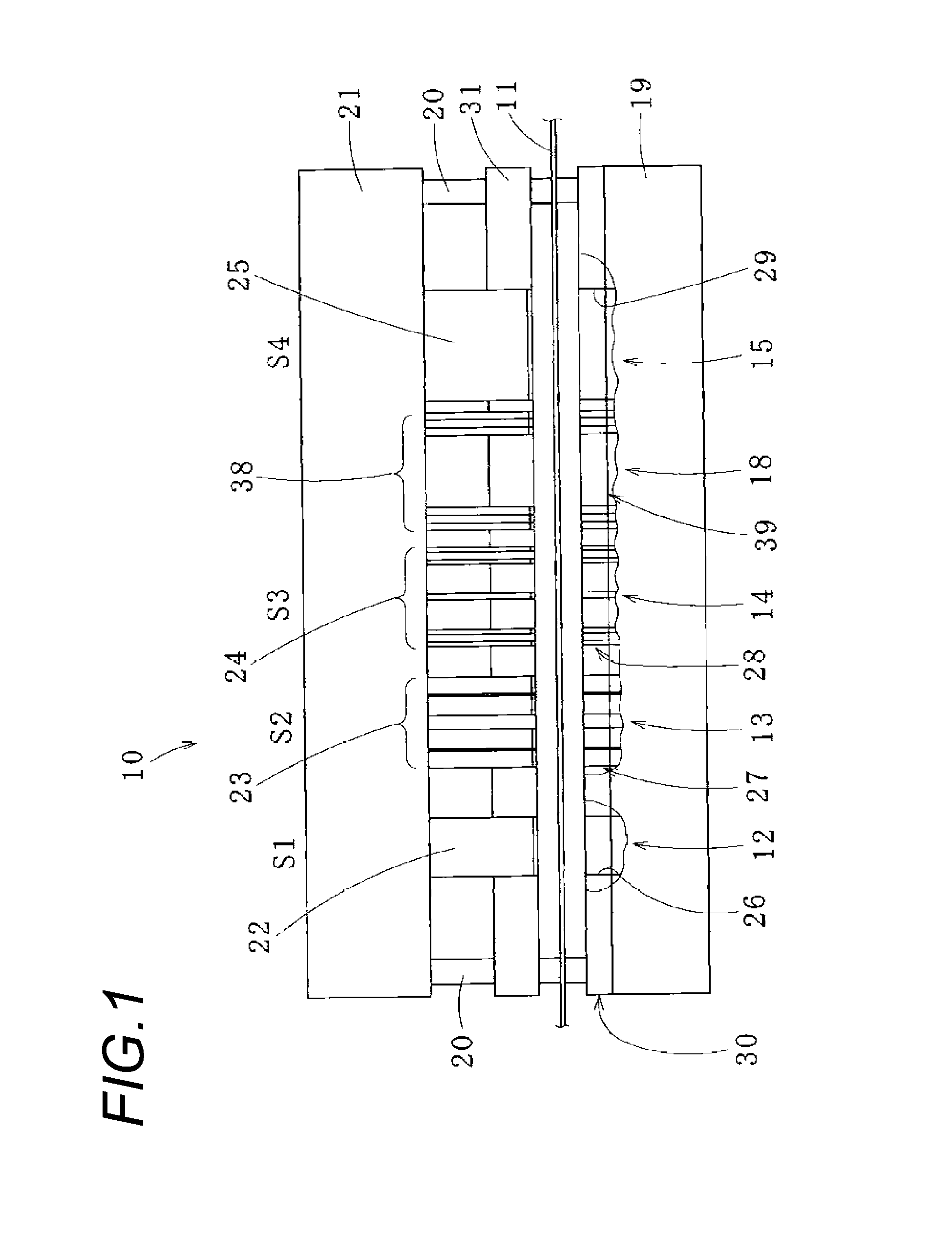
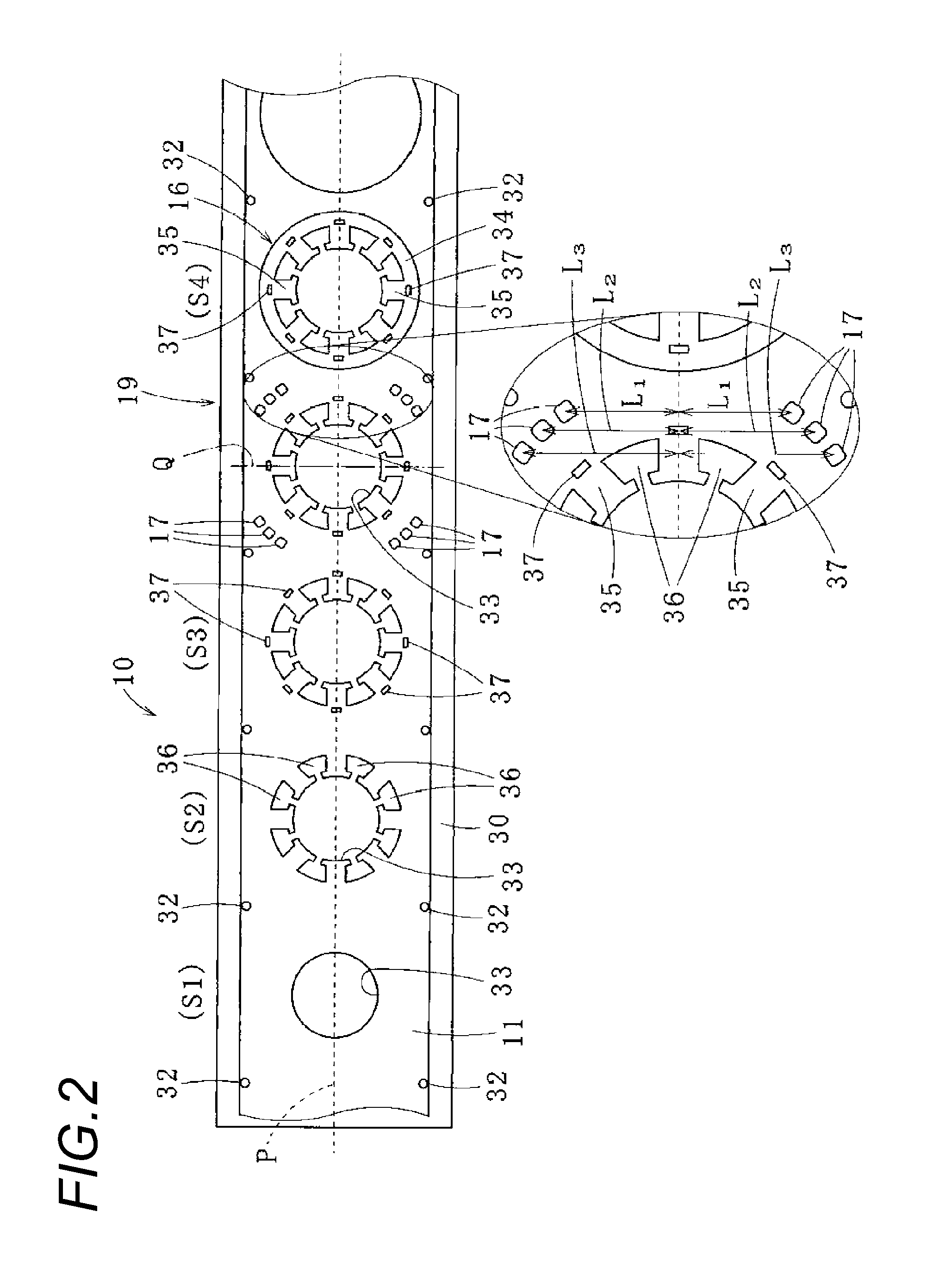
[0038]As shown in FIG. 1, a blanking die apparatus 10 according to an embodiment of the present invention is, for example, a blanking die apparatus for manufacturing a stator laminated iron core, in which a belt-shaped workpiece 11 (electromagnetic steel plate) fed progressively in the longitudinal direction is subjected to specific blanking operations using cutting tools 12 to 15 arranged in multiple machining stations S1 to S4 and is then subjected to contour blanking to thereby form core pieces 16 (see FIG. 2), and the core pieces 16 are next crimped and laminated to thereby form a laminated iron core. The blanking die apparatus 10 further includes auxiliary cutting tools 18 which, simultaneously with the operations of the cutting tools 12 to 15 of the machining stations S1 to S4, are used to form disposal holes 17 (see ...


PUM

PropertyMeasurementUnit
Widthaaaaaaaaaa

Abstract

A laminated iron core manufacturing method in a blanking die apparatus having multiple machining stations is provided. The method includes feeding a belt-shaped workpiece progressively in a longitudinal direction in the blanking die apparatus, operating cutting tools provided in the respective machining stations simultaneously to perform predetermined blanking operations on the progressively fed workpiece and finally perform a contour blanking operation on the workpiece so as to form core pieces, and laminating the core pieces within or outside the blanking die apparatus to thereby manufacture a laminated iron core. An auxiliary cutting tool is operated to form a disposal hole by partly blanking a scrap forming area of the workpiece simultaneously with the operations of the cutting tools of the multiple machining stations, to thereby secure a load balance of the blanking die apparatus in the feeding direction.

Description

CROSS REFERENCE TO RELATED APPLICATIONS[0001]This application is based upon and claims the benefit of priorities of Japanese Patent Applications No. 2013-231259 filed on Nov. 7, 2013 and No. 2014-204095 filed on Oct. 2, 2014, the contents of which are incorporated herein by reference in its entirety.BACKGROUND OF THE INVENTION[0002]1. Field of the Invention[0003]The present invention relates to a laminated iron core manufacturing method and a blanking die apparatus.[0004]2. Description of the Related Art[0005]Generally, a blanking die apparatus 80, as shown in FIG. 4, includes an upper die tool 82 and a lower die tool 83 connected to each other by multiple guide posts 81 and also has multiple machining stations S1 to S6 (the number of machining stations is arbitrary) respectively for blanking a belt-shaped workpiece 84 (for example, an electromagnetic steel plate) progressively. Each of the machining stations S1 to S6 has a die 85 fixed to the lower die tool 83 and a punch 87, paire...

Claims


Application Information

Patent Timeline
IPC IPC(8): H02K15/02
CPCH02K15/02H02K15/022Y10T29/49012Y10T83/6484Y10T29/53161B21D28/14
Inventor SHIMIZU, TAKAHIROTANIISHI, HIRONOSUKE
Owner MITSUI HIGH TEC INC
Why Eureka
Try Eureka