Eureka AIR delivers breakthrough ideas for toughest innovation challenges, trusted by R&D personnel around the world.

Ribbed foundation for superstructures and method for producing the foundation

Inactive Publication Date: 2015-05-07
TAMP HYBRID TOWERS
View PDF16 Cites 10 Cited by
  • Summary
  • Abstract
  • Description
  • Claims
  • Application Information

AI Technical Summary

Benefits of technology

The new foundation aims to save money and speed up the construction of superstructures by improving the time it takes to complete the foundation.

Problems solved by technology

European patent application EP1074663 is known, for example, which discloses an example of a foundation with three stabilizing members arranged symmetrically around a central support, with the drawback of having very little surface for contacting with the terrain, with the subsequent increase in stress applied on the terrain and in settlements.
It is a very complex solution to implement and presents serious questions concerning its structural performance.
However, such foundations have the drawback of being quite large, so the use of steel and concrete as well as the volume of earth that is removed is extraordinarily high, all of which noticeably increases the economic cost of the structure.
This problem is very real due to the tendency to building more and more high-powered wind turbines with a shaft height of 120 m, which produces a cost increment for producing the foundation, making it a weak competitor for all these conventional systems of producing reinforced-concrete foundations.

Method used


Image

  • Ribbed foundation for superstructures and method for producing the  foundation
  • Ribbed foundation for superstructures and method for producing the  foundation
  • Ribbed foundation for superstructures and method for producing the  foundation

Examples


Embodiment Construction

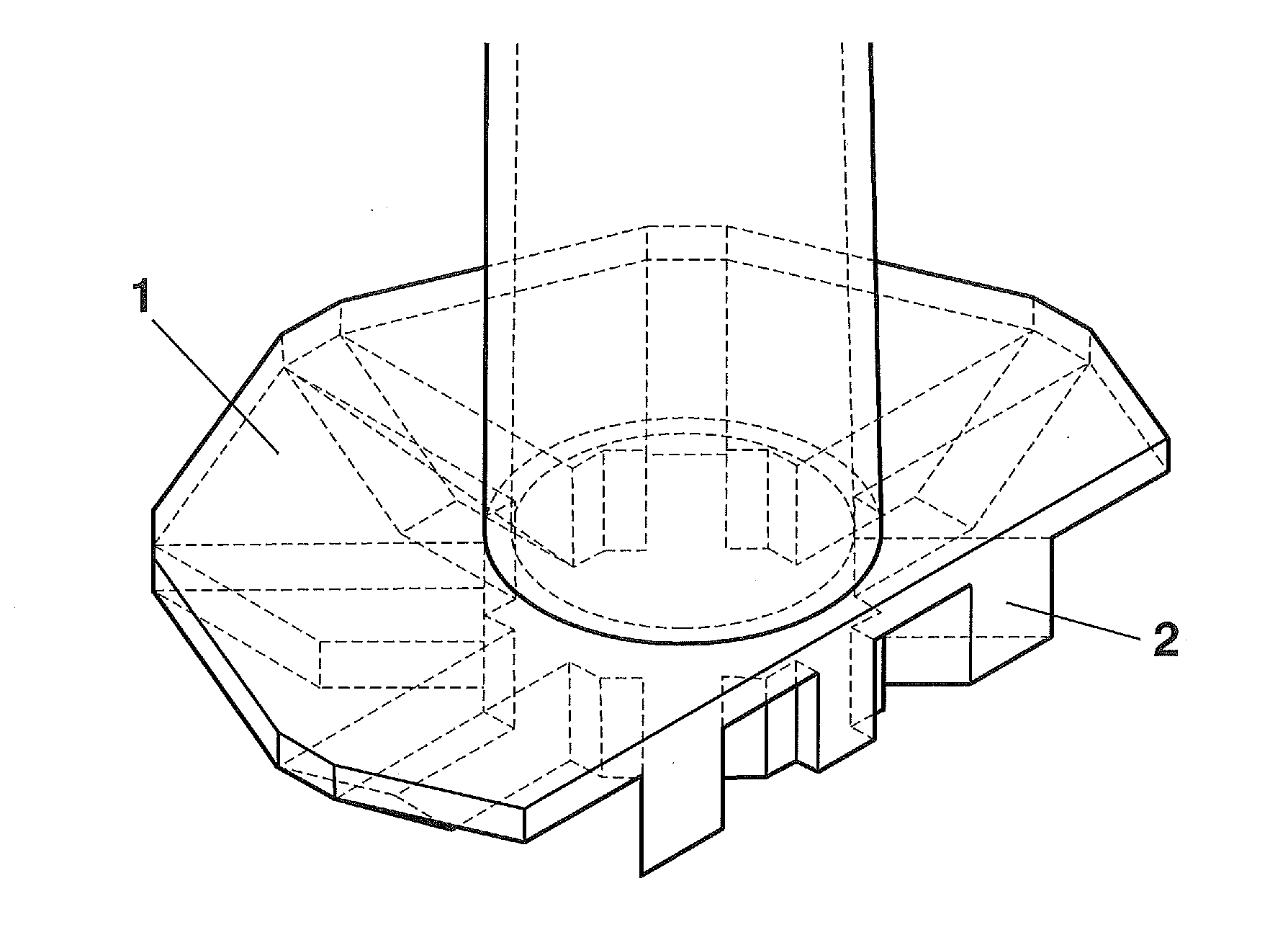
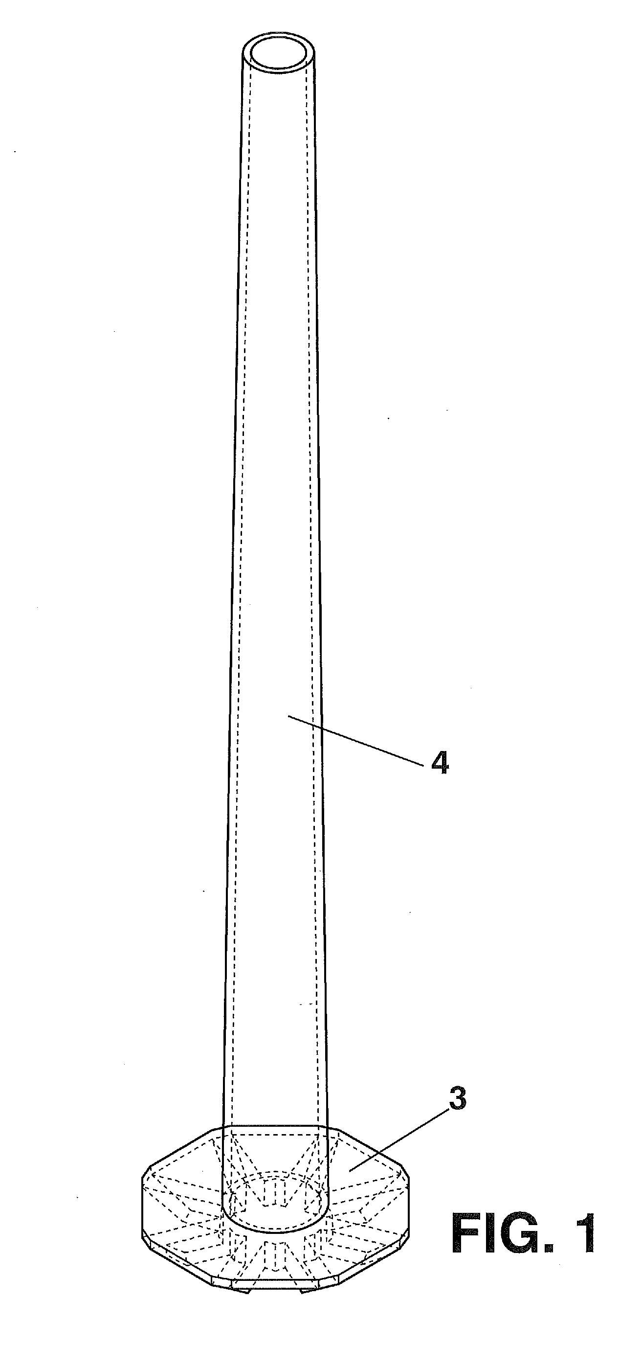
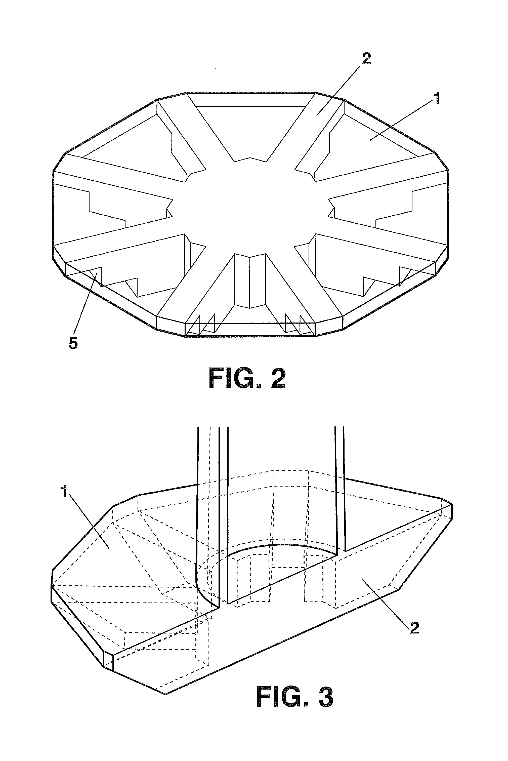
[0010]In an attempt to overcome the mentioned problems in the state of the art, the present invention presents a solution formed by an upper reinforced-concrete slab poured “in situ” having a polygonal or circular footprint and which is made rigid at the bottom by means of reinforced-concrete ribs of a rectangular or trapezial cross-section which are arranged radially stemming from a central core. The concrete for the ribs is poured directly on the previously excavated terrain, whereas the slab rests on the terrain that has not been removed, acting as permanent formwork.

[0011]The solution consisting of an upper slab and ribs making the slab rigid at the bottom refers to the arrangement of both elements with respect to the surface of the ground where the foundation is built, where the slab is arranged first and the stiffening ribs would be arranged below the slab.

[0012]The advantages of this foundation are[0013]The volume of concrete used is much less than in the conventional solutio...


PUM


Abstract

The present invention relates to a reinforced-concrete foundation system for erecting superstructures that transmit high axial loads, shearing forces and / or flexural moments at individual points, such as, for example, wind turbines. The foundation that is the subject matter of the present invention is formed by an upper reinforced-concrete slab poured “in situ”, of polygonal or circular footprint, and which is made rigid at the bottom by means of reinforced-concrete ribs of rectangular or trapezial cross section which are arranged radially. The method makes provision for said ribs to be produced from concrete “in situ” or, alternatively, by means of prefabricated elements, always working, jointly with the upper slab. This new foundation considerably reduces the costs of forming traditional foundations for this type of superstructure, by considerably improving completion deadlines.

Description

OBJECT OF THE INVENTION[0001]The present invention relates to a reinforced-concrete foundation system for erecting superstructures that transmit high axial loads, shearing forces and / or bending moments at individual points, such as wind turbines.[0002]The foundation object of the present invention is formed by an upper reinforced-concrete slab poured “in situ”, having a polygonal or circular footprint, and which is made rigid at the bottom by means of reinforced-concrete ribs of a rectangular or trapezial cross-section which are arranged radially. The method envisages said ribs being made with concrete “in situ”, or alternatively by means of prefabricated elements, always working integrally with the upper slab.[0003]This new foundation seeks to considerably reduce costs for building conventional foundations for such superstructures by considerably improving completion deadlines.BACKGROUND OF THE INVENTION[0004]The type of foundation most frequently used today for superstructures suc...

Claims


Application Information

Patent Timeline
IPC IPC(8): E02D27/42E02D27/01E02D27/08E02D27/02
CPCE02D27/42E02D27/08E02D27/016E02D27/02E02D27/425
Inventor ABAD HUBER, CESARFRANCO REY, JORGE
Owner TAMP HYBRID TOWERS
Why Eureka
Eureka Blog
Learn More