System and method for using a rate of decay measurement for real time measurement and correction of zero offset and zero drift of a mass flow controller or mass flow meter

a technology of mass flow rate and decay measurement, applied in the direction of liquid/fluent solid measurement, process and machine control, instruments, etc., can solve the problems of low yield or even total loss of the product being manufactured

Active Publication Date: 2015-05-07
ILLINOIS TOOL WORKS INC
View PDF8 Cites 18 Cited by
  • Summary
  • Abstract
  • Description
  • Claims
  • Application Information

AI Technical Summary

Benefits of technology

[0008]As an example, the disclosed embodiments include a mass flow controller for controlling a flow of a fluid, the mass flow controller comprising: an inlet for receiving the fluid; a flow path in which the fluid passes through the mass flow controller; a mass flow sensor for providing a signal corresponding to mass flow of the fluid through the flow path; an adjustable valve for regulating the flow of the fluid out of an outlet of the mass flow controller; a controller configured to apply a valve control signal to adjust the adjustable valve to a desired valve position to control the flow of the fluid out of an outlet of the mass flow controller; a communication interface for communicating with a tool controller; and at least one processing component configured to execute instructions to perform an in-situ rate of decay measurement to identify valve leak issues.
[0009]As another example, the disclosed embodiments include a mass flow controller comprising an inlet for receiving the fluid from a gas delivery line having an external isolation valve upstream of the inlet; a flow path in which the fluid passes through the mass flow controller; a mass flow sensor for providing a signal corresponding to mass flow of the fluid through the flow path; an adjustable valve for regulating the flow of the fluid out of an outlet of the mass flow controller; a controller configured to apply a valve control signal to adjust the adjustable valve to a desired valve position to control the flow of the fluid out of an outlet of the mass flow controller; an internal valve configured to receive a first pneumatic line coupled to a tool pilot valve and couple a second pneumatic line from the internal valve to an external isolation valve upstream of the inlet; and at least one processing component configured to execute instructions to perform an in-situ rate of decay measurement after executing instructions to close the external isolation valve by using the internal valve to block airflow being received through the first pneumatic line.
[0010]The disclosed embodiments also include a mass flow controller for controlling a fl

Problems solved by technology

Mass flow controllers and mass flow meters that drift (e.g. due to aging) or get clogged (e.g. due to contamination) will cause a loss of repeatability that causes the process characteristics to change and

Method used


Image

  • System and method for using a rate of decay measurement for real time measurement and correction of zero offset and zero drift of a mass flow controller or mass flow meter
  • System and method for using a rate of decay measurement for real time measurement and correction of zero offset and zero drift of a mass flow controller or mass flow meter
  • System and method for using a rate of decay measurement for real time measurement and correction of zero offset and zero drift of a mass flow controller or mass flow meter

Examples


Embodiment Construction

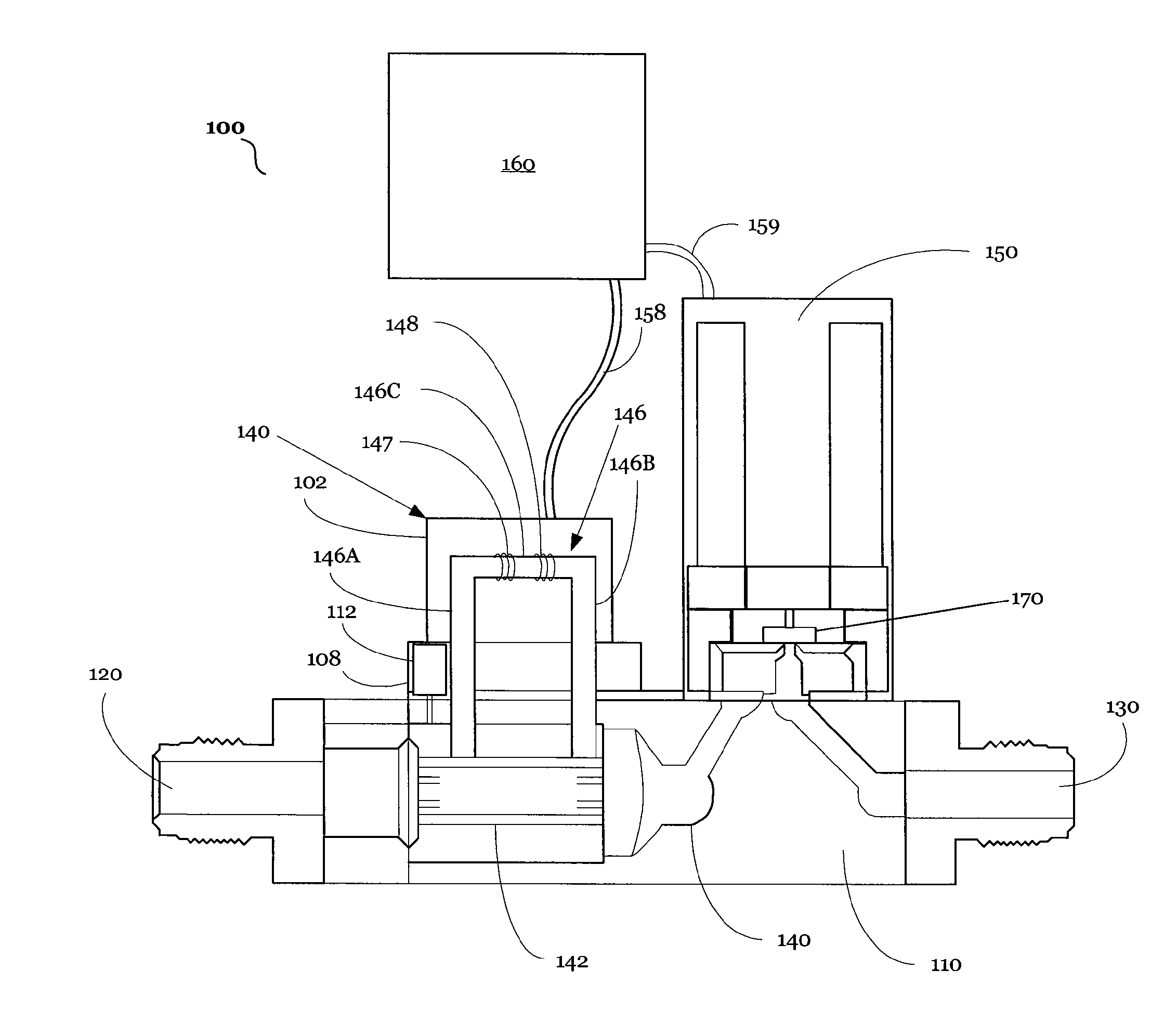
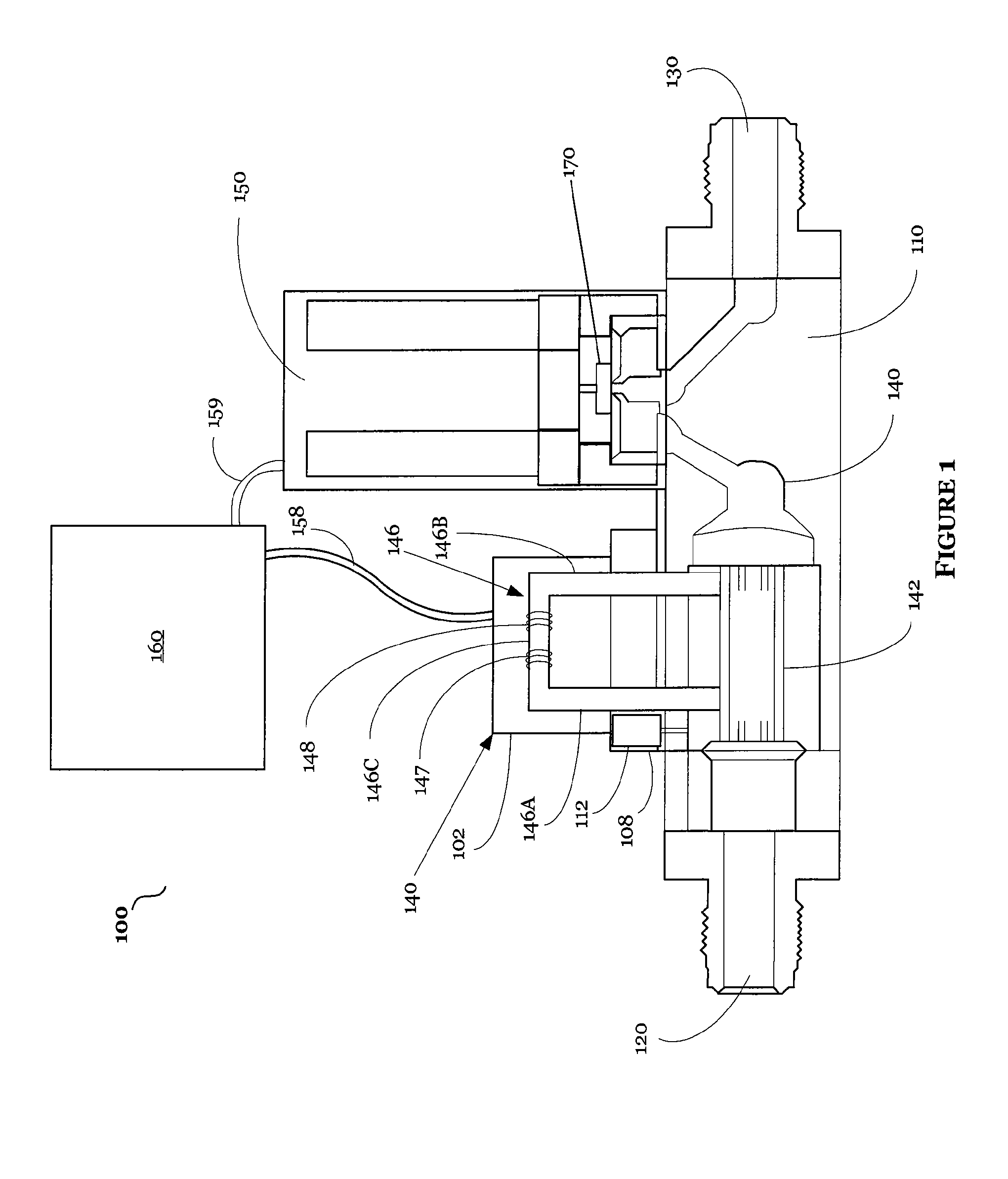
[0030]The disclosed embodiments include a system, method, and apparatus for providing a self-validating mass flow controller that utilizes at least one of the disclosed self-validating procedures for providing real time in-situ correction of a mass flow controller's output to account for zero offset or zero drift. This will enable the mass flow controller to provide real time accurate information without requiring any tool down time to make the measurements.

[0031]The disclosed embodiments and advantages thereof are best understood by referring to FIGS. 1-16 of the drawings, like numerals being used for like and corresponding parts of the various drawings. Other features and advantages of the disclosed embodiments will be or will become apparent to one of ordinary skill in the art upon examination of the following figures and detailed description. It is intended that all such additional features and advantages be included within the scope of the disclosed embodiments. Further, the il...


PUM


Abstract

The disclosed embodiments include a method, apparatus, and computer program product for providing a self-validating mass flow controller or mass flow meter. For example, in one embodiment, a self-validating mass flow controller is disclosed that does not require any software modification to a tool/tool controller in which the mass flow controller is being utilized. In other embodiments, a self-validating mass flow controller is disclosed that does not require any hardware or mechanical changes to an existing mass flow controller. Still, the disclosed embodiments further include a self-validating mass flow controller that is configured to determine valve leak and sensor offset simultaneously for performing real time in-situ correction of a mass flow controller's output for zero offset or zero drift in the presence of valve leak.

Description

BACKGROUND OF THE INVENTION[0001]1. Field of the Invention[0002]The present invention relates generally to methods and systems for determining the mass flow rate of a fluid, and more particularly to the operation of mass flow controllers (MFCs) and mass flow meters (MFMs).[0003]2. Discussion of the Related Art[0004]Many industrial processes require precise control of various process fluids. For example, in the semiconductor industries, mass flow meters (MFMs) are used to precisely measure the amount of a process fluid that is introduced to a process chamber. In addition to measuring the mass flow, mass flow controllers (MFCs) are used to precisely measure and control the amount of a process fluid that is introduced to a process chamber. It is to be understood that the term fluid as used herein applies to any type of gas or vapor to which controlled flow may be of interest.[0005]Mass flow controllers and mass flow meters have well defined performance criteria that are guaranteed by t...

Claims


Application Information

Patent Timeline
IPC IPC(8): G01F25/00
CPCG01F25/0007G01F5/00G05D7/0635G01F1/6847G01F25/15G01F25/10G01F1/88
Inventor BANARES, BERWINVALENTINE, BILLLULL, JOHNKEHOE, ANTHONYELLEC, CHRIS
Owner ILLINOIS TOOL WORKS INC
Why Eureka
Try Eureka