
Device for calculating amount of reduced fuel consumption, and program for displaying calculation, as well as device for calculating amount of reduced co2 exhaust, and program for displaying calculation

Inactive Publication Date: 2015-05-07
JAPAN ECO SUPPORTER +1
View PDF0 Cites 5 Cited by
  • Summary
  • Abstract
  • Description
  • Claims
  • Application Information

AI Technical Summary

Benefits of technology

The carbon dioxide emission reduction amount calculation and display program allows a computer to input baseline data and project data of a heating appliance, such as a dryer, before and after installing a combustion improvement device that improves fuel combustion in an internal combustion engine. The program calculates the baseline fuel consumption efficiency and the baseline consumption amount, which are used to determine the carbon dioxide emission reduction amount. This program can help reduce carbon dioxide emissions from combustion appliances and promote energy management.

Problems solved by technology

The amount of greenhouse gas emissions of many countries has been increasing every year, and reduction of these emissions is an important issue.
However, with the use of improvement devices like the one mentioned above, it is difficult to quantify and to visualize the improvement of fuel consumption (fuel consumption reduction amount) and the CO2 emission reduction amount.
However, fuel consumption efficiencies constantly fluctuate depending on driving conditions.
For example, regardless whether” a combustion improvement device providing an obvious combustion efficiency improvement has been mounted, the fuel consumption efficiency is decreased if engine idling is not stopped.
Moreover, regardless whether” a combustion improvement device is mounted on a vehicle operating on local roads, the fuel consumption efficiency may be less than a vehicle operating on a highway without a combustion improvement device.
In this way, the influence on fuel consumption efficiency by driving conditions is significant, and effects obtained by mounting the combustion improvement device could not otherwise be obtained.
That is, any improvements in fuel consumption efficiency could not have been determined just with the mounting of the combustion improvement device.

Method used


Image

  • Device for calculating amount of reduced fuel consumption, and program for displaying calculation, as well as device for calculating amount of reduced co2 exhaust, and program for displaying calculation
  • Device for calculating amount of reduced fuel consumption, and program for displaying calculation, as well as device for calculating amount of reduced co2 exhaust, and program for displaying calculation
  • Device for calculating amount of reduced fuel consumption, and program for displaying calculation, as well as device for calculating amount of reduced co2 exhaust, and program for displaying calculation

Examples


examples

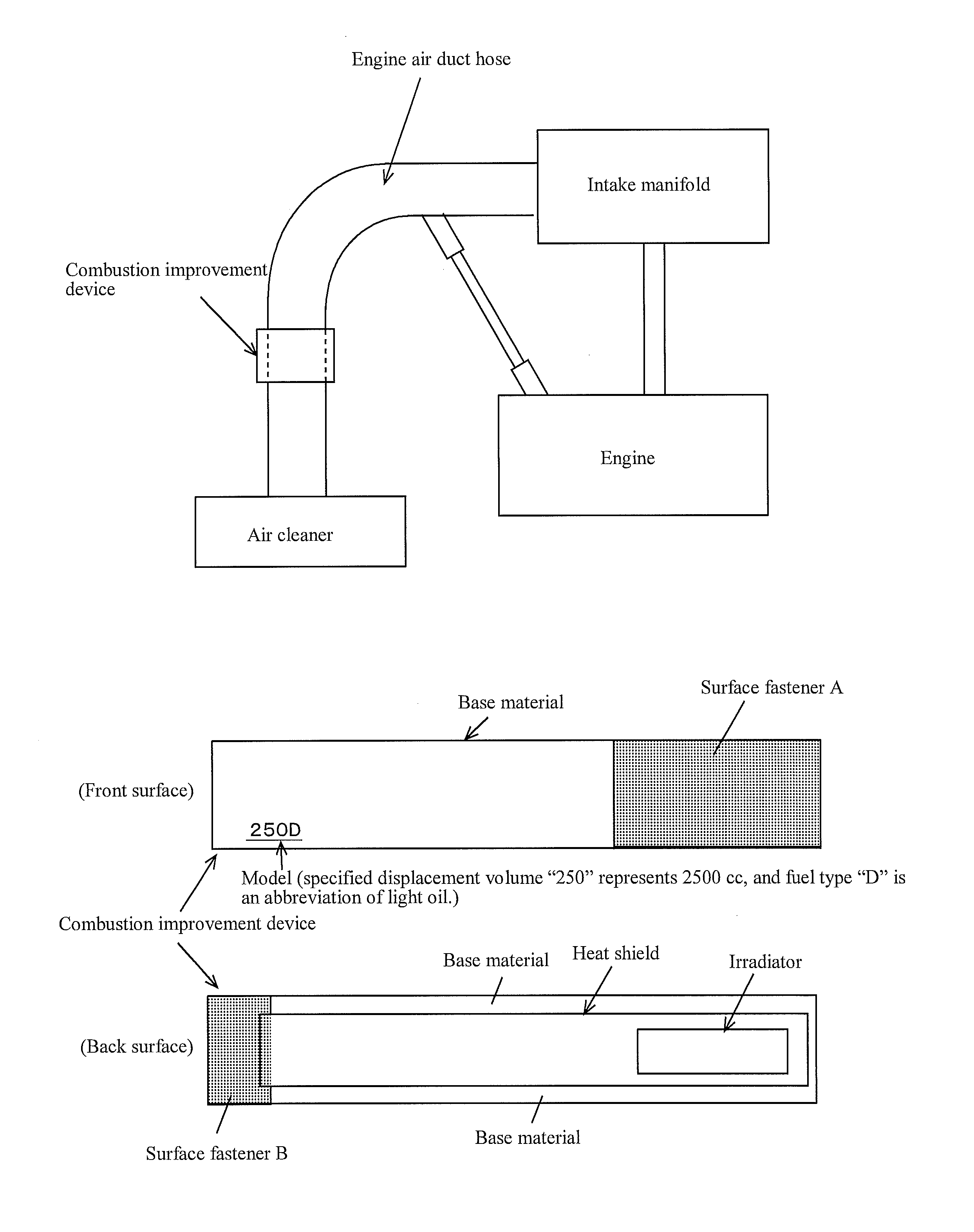
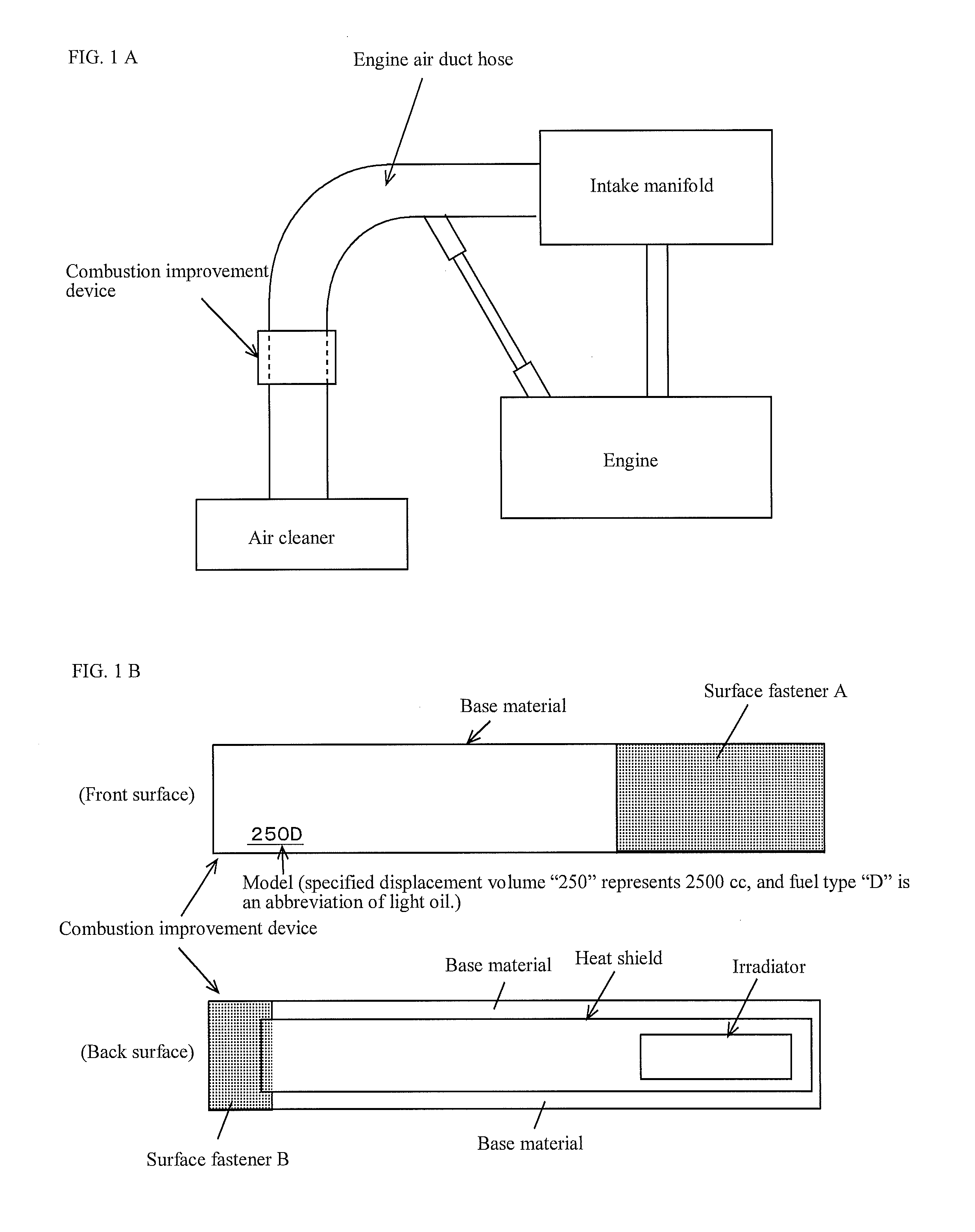
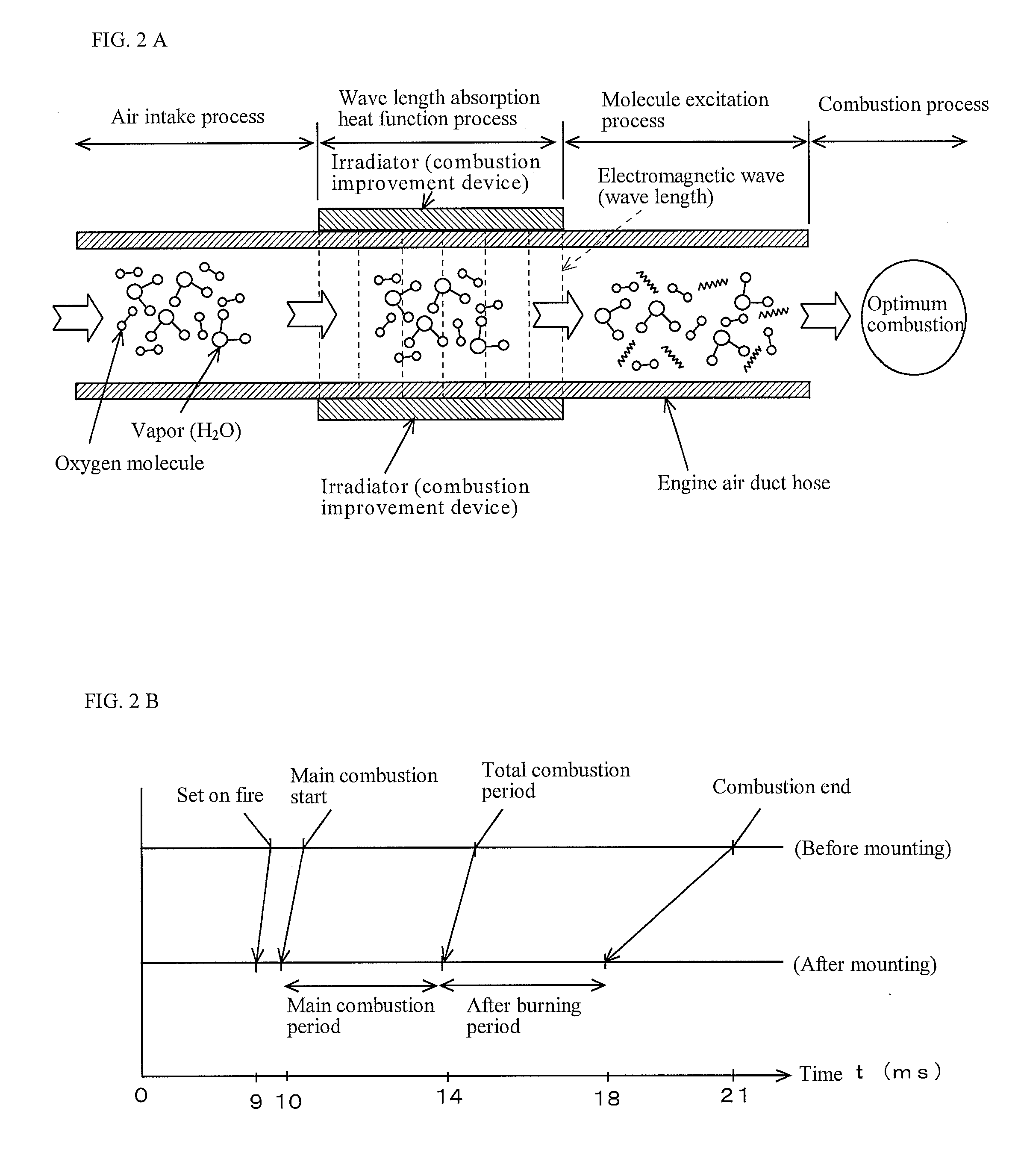
[0061]The fuel consumption reduction amount calculation device and the carbon dioxide emission reduction amount calculation device according to the present disclosure are explained based on the drawings. FIG. 1(a) and FIG. 1(b) are schematic diagrams showing an example of the combustion improvement device used in the present disclosure. FIG. 2A and FIG. 2B are schematic diagrams showing the principle of the combustion improvement device and combustion improvement effect used in the present disclosure. FIG. 2A is a schematic diagram showing the principle of the combustion improvement device, and FIG. 2B is a schematic diagram showing the combustion improvement effect.

[0062]FIG. 3 is a block diagram of a fuel consumption reduction amount calculation device and the carbon dioxide emission reduction amount calculation device according to the present disclosure.

[0063]FIG. 4 is a flow chart of the fuel consumption reduction amount calculation and display program and the carbon dioxide emi...


PUM


Abstract

PROBLEM TO BE SOLVED: To provide a fuel consumption reduction amount calculation device, a fuel consumption reduction amount calculation and display program, a carbon dioxide emission reduction amount calculation device, and a carbon dioxide emission reduction amount calculation and display program, that digitize the fuel consumption reduction amounts or CO2 emission reduction amounts of a vehicle or a drier or the other heating appliances.SOLUTION: A fuel consumption reduction amount calculation device 10 inputs base line data 14 and 16 of a vehicle before mounting a combustion improvement device and project data 18 and 20 of the vehicle after mounting the combustion improvement device, and displays a value calculated by subtracting annual fuel consumption amount taken from project data from a value calculated by dividing annual travel distance taken from the project data by the fuel consumption rate taken from the base line data. Also, a carbon dioxide emission reduction amount calculation device 34 displays a value calculated by subtracting an emission amount that is calculated by multiplying an emission coefficient by the annual fuel consumption amount taken from project data from the emission amount calculated by multiplying the annual fuel consumption amount taken from the project data by the annual travel distance taken from the project data divided by the fuel consumption rate taken from the base line data.

Description

TECHNICAL FIELD[0001]The present disclosure relates to a fuel consumption reduction amount calculation device, a calculation and display program thereof, a carbon dioxide emission reduction amount calculation device, and a calculation and display program thereof that calculate the fuel consumption reduction amount or the carbon dioxide CO2 emission reduction amount for which a combustion improvement device, that improves burning of a fuel in an internal combustion engine of a vehicle or other heating appliances such as a dryer and the like, has been installed.BACKGROUND ART[0002]The amount of greenhouse gas emissions of many countries has been increasing every year, and reduction of these emissions is an important issue. Much of the greenhouse gases emitted by a transportation section is from vehicles.[0003]Conventionally, combustion improvement devices are designed to improve fuel combustion and can reduce fuel consumption and CO2 emissions by installing the improvement device on a...

Claims


Application Information

Patent Timeline
IPC IPC(8): G01F9/00
CPCG01F9/00G01F9/008
Inventor SHIKANAI, YASUSHITAGUCHI, TOMIO
Owner JAPAN ECO SUPPORTER
Learn More