Catalytic burner

a burner and catalytic technology, applied in the field of burners, can solve the problems of significant carbon generation, limited heating rate of substrates, and limited rate of oxidation upon mixing, so as to increase the lifetime of burners, reduce the rate at which the wick is degraded, and enhance the combustion of fuel.

Active Publication Date: 2018-08-07
STONEWICK LLC
View PDF40 Cites 0 Cited by
  • Summary
  • Abstract
  • Description
  • Claims
  • Application Information

AI Technical Summary

Benefits of technology

[0012]Preheating of the fuel gases to obtain flameless combustion without a catalyst would result in significant generation of carbon unless a carbon formation suppressant is included in the fuel gas stream. The need to provide such a carbon formation suppressant is therefore avoided by operating the burner in the presence of a catalyst.
[0017]In an embodiment of the invention, the fuel may contain one or more chemical compounds. In such an embodiment, the fuel / chemical compound mixture comes into intimate contact with the catalyst to transform the chemical compound(s) in some fashion. In certain embodiments, the transformation of the chemical compound(s) enhances the combustion of the fuel.
[0018]In some embodiments, by carefully selecting the material from which the tube body of the catalytic burner is constructed, the wick can be situated so that it is not in direct contact with the tube body. This lack of contact between the wick and the tube body greatly reduces the rate at which the wick is degraded and increases the lifetime of the burner. If loss of fuel flow occurs due to wick degradation, the degraded wick can easily be replaced with a new wick without loss of function. Although the fragrance may still be partially degraded and remain on the wick, the wick continues to function.
[0020]According to an embodiment of the invention, the catalytic burner is composed of three main parts: an absorbent wick, a tube body, and a catalyst that has been deposited on a suitable substrate. The construction of the burner and the geometry of the supported catalyst, allow the catalytic burner to operate continuously for extended periods of time. In certain embodiments of the invention, a catalytic burner that is constructed and operated as set forth herein can operate continuously for around 184 hours.

Problems solved by technology

Generally, flameless combustion is accomplished by preheating combustion air and fuel gas sufficiently that when the two streams are combined the temperature of the mixture exceeds the auto-ignition temperature of the mixture, but to a temperature less than that which would result in the oxidation upon mixing being limited by the rate of mixing.
Preheating of the fuel gases to obtain flameless combustion without a catalyst would result in significant generation of carbon unless a carbon formation suppressant is included in the fuel gas stream.
The rate of heating the substrate will typically be limited by the thermal gradients the burner can tolerate.

Method used


Image

  • Catalytic burner
  • Catalytic burner
  • Catalytic burner

Examples


Embodiment Construction

[0033]Various embodiments of the present invention will now be described more fully with reference to the accompanying drawings. The invention may, however, be embodied in many different forms and should not be construed as limited to the embodiments set forth herein.

[0034]The use of start-up oxidants and / or fuels is preferred only until the catalyst has been heated to a temperature sufficient to enable operation with a fuel of choice and air as the oxidant. According to embodiments of the invention, methanol, ethanol, propanol, butanol, dimethyl ketone, ethyl acetate, methane, ethane, propane, butane, propylene glycol, dimethylformamide or any other suitable fuel known in the prior art can be used as the working fuel in embodiments of the invention.

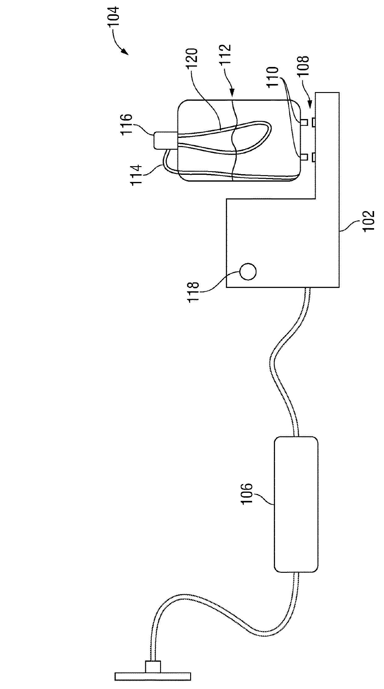
[0035]FIG. 1 illustrates a system 100 for electrical activation of a catalytic burner. The system 100 includes a controller unit 102, a catalytic burner device 104, and a power supply 106. The controller unit 102 includes a pair of elect...


PUM

PropertyMeasurementUnit
open porosityaaaaaaaaaa
temperatureaaaaaaaaaa
temperaturesaaaaaaaaaa

Abstract

A catalytic burner with electric start. The method of using the catalytic burner comprises an electric-start device that may actuated via a switch or remotely via radio signal.

Description

CROSS REFERENCES TO RELATED APPLICATIONS[0001]This application is a continuation-in-part of application Ser. No. 13 / 843,214, filed on Mar. 15, 2013, which is a continuation-in-part of application Ser. No. 11 / 974,455 filed on Oct. 12, 2007, which claims the benefit of U.S. Provisional Application 60 / 851,235, filed Oct. 12, 2006, each of which is incorporated herein by reference as if fully set forth herein.FIELD OF THE INVENTION[0002]The invention relates to a burner comprising an electrically activated catalyst that provides flameless combustion of fuels.BACKGROUND OF THE INVENTION[0003]The invention represents an improvement over existing technology in use with burners, such as those described in U.S. Pat. No. 6,144,801, U.S. Pat. No. 6,451,841, U.S. Pat. No. 6,537,061, U.S. Pat. No. 6,814,929, U.S. 20050037309 and U.S. 20040265762. The aforementioned systems are composed of a burner, fuel, fuel reservoir, and a wick. The burners are composed of three main components: a porous cera...

Claims


Application Information

Patent Timeline
Patent Type & Authority Patents(United States)
IPC IPC(8): F23C13/02F23D3/02F23D11/44F23Q25/00F23Q21/00F23D3/24F23Q11/00F23D14/18F23D5/12H04W4/80B01J32/00G08C17/02
CPCF23D3/02F23C13/02F23D3/24F23D5/126F23D11/448F23D14/18F23Q21/00F23Q25/00F23Q11/00H04W4/80B01J32/00F23D2203/107F23D2900/03081G08C17/02F23Q2/282
Inventor PISKLAK, THOMAS J.
Owner STONEWICK LLC
Why Eureka
Try Eureka