Magnetic Platinum Catalyst and Method of Making and its Application as an Engine Fuel Enhancer

a platinum catalyst and platinum technology, applied in the field of metal material technology, can solve the problems of engine energy consumption and gas waste, methods that fail to treat the major issue in engine combustion, negative impact on engine performance, etc., and achieve the effects of improving the degradation of organic compounds, and enhancing the energy of fuel oil passing

Inactive Publication Date: 2013-06-20
CHEN SHI MIN +1
View PDF0 Cites 0 Cited by
  • Summary
  • Abstract
  • Description
  • Claims
  • Application Information

AI Technical Summary

Benefits of technology

[0015]This engine fuel oil energy enhancer is attached to the oil supply line like a duplex, with the magnetic north (N) pole of one unit facing the magnetic (S) pole of the other. It can then enhance the energy of the fuel oil passing through the oil supply line. This engine fuel oil energy enhancer can also be placed into the oil tank to enhance the energy of the fuel oil.
[0016]Through the movement of the earth's crust, mother nature has given extra power to the platinum group metals. They are constantly radiating this power. The energy enhancement of the engine fuel enhancer to the fuel oil is indeed catalyzing the fuel oil by introducing the special energy in the platinum metal into the fuel oil through the magnet particle flux. The catalyzing power of the platinum metals will motivate the oil electrons in the molecule valence zone to transit to a higher zone. The inter-zone electric flow caused by this electron transit makes the oil molecules more active and generates more oxygen negative ions and hydro-oxy free radicals. This improves the degradation of organic and inorganic chemicals, thus improves the combustion efficiency of the engine fuel oil. Eventually, improved fuel oil combustion efficiency makes cleaner combustion of the fuel oil, less hazardous gases like CO, HC, and NO are generated, and more power is produced. In addition, because the fuel oil is catalyzed to have more power, the accumulated carbon in the engine (the unburned colloid attached to the inner wall of the engine) will be oxidized to combustion. It cleanses the cylinder and protects it, and improves power output. The present invention's ability to save energy, reduce discharge, and reduce waste is mainly achieved by making the hard-to-combust portion of the fuel oil burn more thoroughly. Thus less waste and hazardous gases are produced, more power is generated, more mile-per-gallon ratio is achieved, and the energy consumption and waste discharge per mile is reduced.
[0017]In summary, the present invention can significantly reduce fuel use, improve the power output of the engine, significantly reduce the discharge of hazardous gases in engine gas waste, to save energy, reduce discharge, and reduce waste. Through several years of experiments and development, and using neodymium permanent magnetic material as carrier and platinum family rare earth metal catalyst as core, the engine fuel enhancer technology has matured. The engine fuel enhancer of the present invention is attached to the oil supply pipeline as a duplex (N pole faces S pole). It has a good impact in catalyzing the fuel oil that passes through the oil supply pipeline to get more energy. The engine fuel enhancer of the present invention has a stable performance, a long life span, and is safe to use.

Problems solved by technology

Currently, the pollution from the energy consumption and gas waste of engines, especially automobile engines has become one of the major social issues.
Simply improving the engine technology, or improving the treatment of the engine gas waste are limited to changing the engine or re-combustion of the high temperature gases (compounds) produced during incomplete combustion of the engine, such as CO, HC, and NO, to limit the discharge of the gas waste.
These methods fail to treat the major issue in the engine combustion, the fuel oil.
It has a negative impact on the engine's performance, and cannot improve the fuel efficiency.
Thus, it cannot save energy, reduce gas waste gas, and reduce hazardous gases from the root.

Method used


Image

  • Magnetic Platinum Catalyst and Method of Making and its Application as an Engine Fuel Enhancer
  • Magnetic Platinum Catalyst and Method of Making and its Application as an Engine Fuel Enhancer
  • Magnetic Platinum Catalyst and Method of Making and its Application as an Engine Fuel Enhancer

Examples


Embodiment Construction

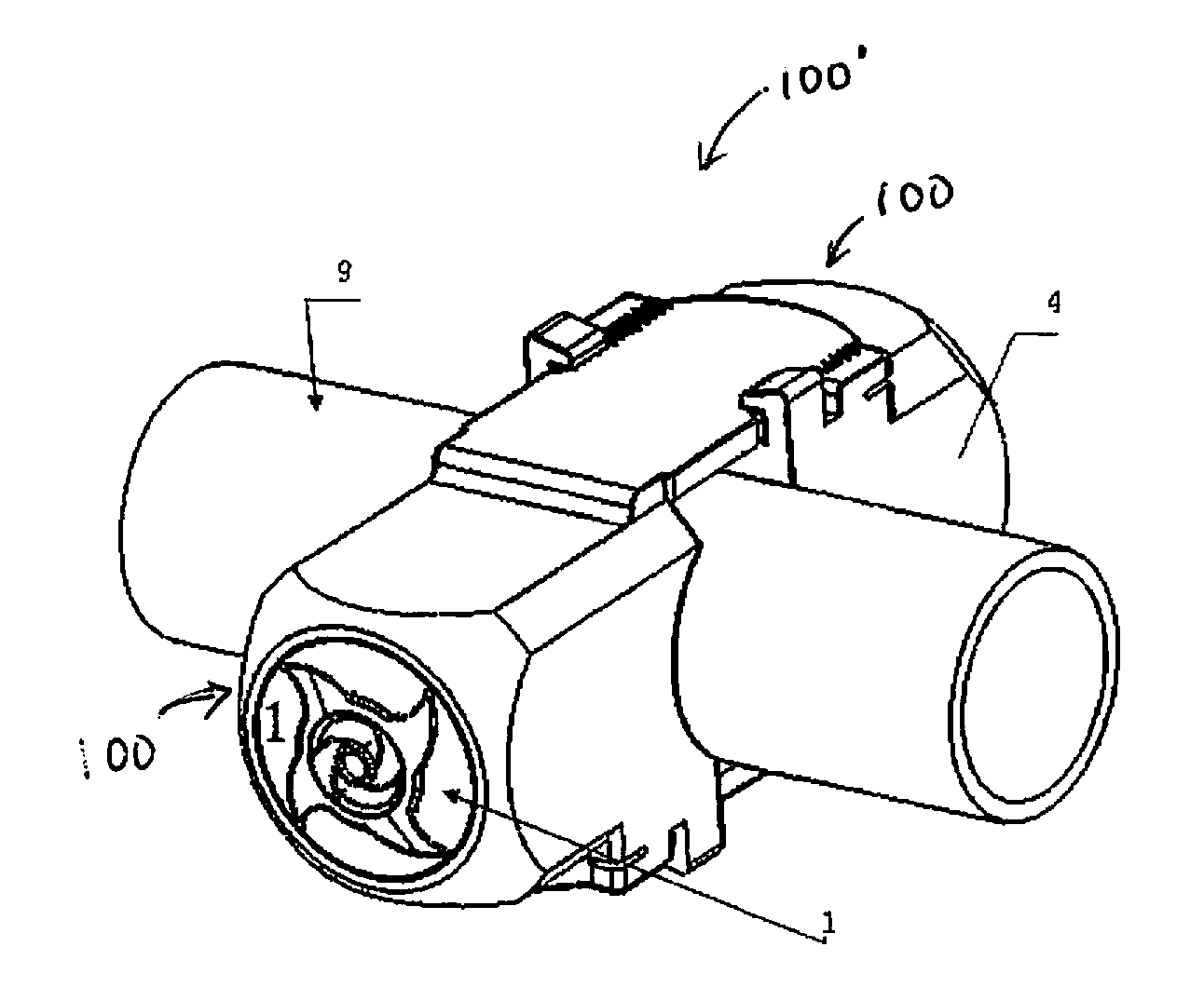
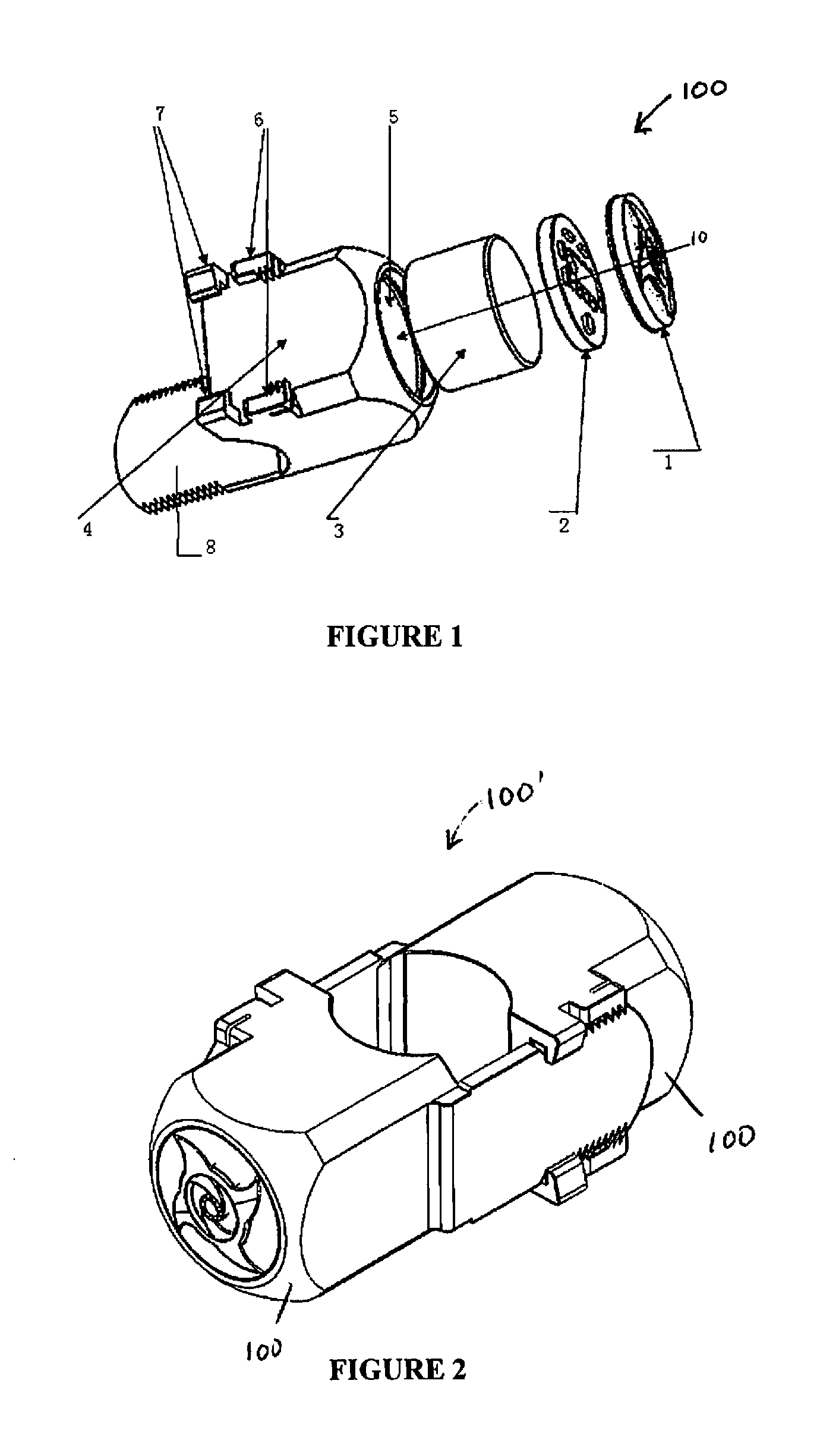
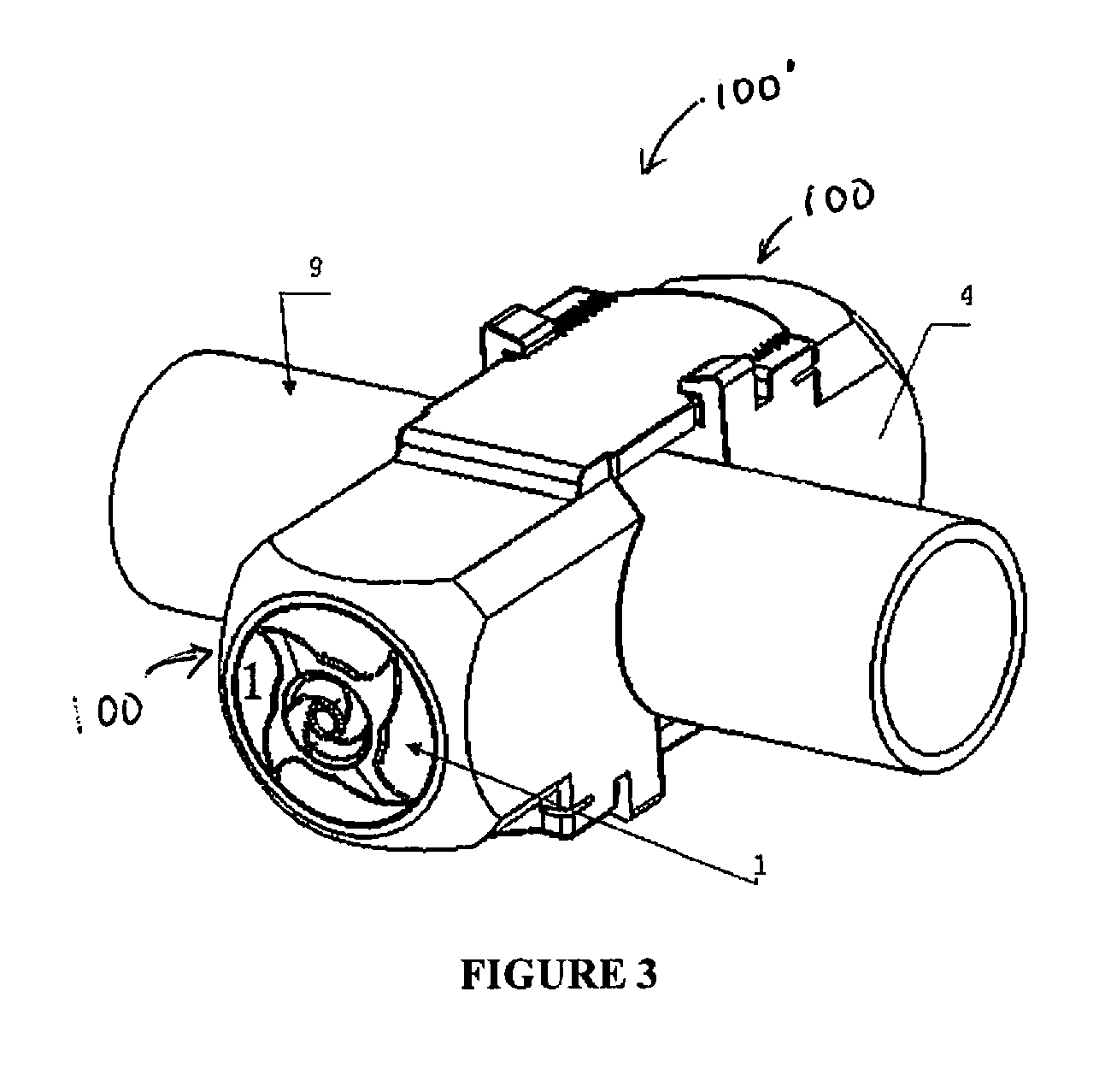
[0023]With reference to the drawings, wherein the same reference number indicates the same element throughout, there is shown in FIGS. 1-3 an engine fuel enhancer 100 of the present invention. The reference numbers in the figures correspond to the following elements: cover 1, functional circuit board 2, magnetic platinum catalyst 3, shell 4, chamber 5, locking teeth 6, docking slot 7, latch with teeth 8, fuel supply line 9, and direction of installation 10.

[0024]One of the manufacturing methods of the magnetic platinum catalyst is as follow:

[0025]Dissolve 6 grams of H2PtCl6(H2PtCl6.6H20) and 4 grams of RhCl3(RhCl3.3H20) into 1000 ml of water. Use oxalic acid to adjust the pH to 4. Settle for 2 hours. Stir for 10 minutes. Heat to 70° C. This is the platinum group metal catalyst acid soaking solution.

[0026]Use powder metallurgy to produce a neutral neodymium magnet alloy. It contains about 39% neodymium. Make it into a cylinder with a diameter of about 13 mm and a length of about 9 mm...


PUM

PropertyMeasurementUnit
lengthaaaaaaaaaa
diameteraaaaaaaaaa
temperatureaaaaaaaaaa

Abstract

A magnetic platinum catalyst and its application as an engine fuel enhancer. The method of making the magnetic platinum catalyst includes: the use of neodymium magnetic alloy containing 25-50% of the neutral neodymium (NdFeB) alloys, processed into a diameter of 13 mm, a length 9 mm cylinder, as a catalyst carrier. The surface of the catalyst carrier is treated with antioxidant. A platinum group metal is used as the catalyst rare earth materials to produce a catalyst acid soaking solution. The solution includes 0.01-0.2% platinum and 0.01-0.15% rhodium. The pH of the solution is adjusted to 4 using oxalic acid. After soaking in the solution, draining, and drying, the carrier is placed in a muffle furnace and baked. The catalyst is firmly attached to the surface of the carrier to form a magnetic platinum catalyst having catalyzing ability. Such catalyst is used in connection with engine fuel to enhance its operation.

Description

FIELD OF THE INVENTION[0001]The present invention is directed to the field of metal material technology. In particular, it applies to a physical enhancement catalyst for fuel powered engines. The present invention uses a permanently magnetic platinum catalyst to apply physical enhancement catalysis in fuel powered automobile engines.BACKGROUND OF THE INVENTION[0002]Currently, the pollution from the energy consumption and gas waste of engines, especially automobile engines has become one of the major social issues. Simply improving the engine technology, or improving the treatment of the engine gas waste are limited to changing the engine or re-combustion of the high temperature gases (compounds) produced during incomplete combustion of the engine, such as CO, HC, and NO, to limit the discharge of the gas waste. These methods fail to treat the major issue in the engine combustion, the fuel oil. Specifically, the current gas waste treatment method only deals with engine discharges. It...

Claims


Application Information

Patent Timeline
Patent Type & Authority Applications(United States)
IPC IPC(8): B01J23/63B01J23/89H05K13/00B23P11/00F02M27/02F02M27/04
CPCB01J23/63F02M27/02F02M27/04B22F9/24C22C1/04Y10T29/49002B01J37/348B01J23/894B01J35/0033B01J37/0213Y10T29/49345C22C2202/02
Inventor CHEN, SHI MINCHEN, YONG SHENG
Owner CHEN SHI MIN
Why Eureka
Try Eureka