Wireless sensor network for measurement of electrical energy consumption

a technology of electrical energy consumption and wireless sensors, applied in the integration of power network operation systems, transmission, sustainable buildings, etc., can solve the problems of low precision, low cost, and inability to meet the needs of users, and achieve the effect of precise measurement of energy consumption

Active Publication Date: 2015-05-07
POLYVALOR S E C
View PDF12 Cites 38 Cited by
  • Summary
  • Abstract
  • Description
  • Claims
  • Application Information

AI Technical Summary

Benefits of technology

[0006]There is described a system to measure the electrical consumption of a household. This system consists of a network of measuring devices that are attached to wires between electrical appliances and circuit breakers and of a communication and processing unit that receives measurement data from the measuring devices. Low precision sensors based on the Hall effect may be used for obtaining precise measurements of energy consumption by providing a casing for the measuring devices that ensures a fixed, known, and precise alignment with respect to the wire to which it is attached. Low precision sensors based on the Hall effect may also be used by performing a correction calibration of measured data.

Problems solved by technology

Some of the challenges of such systems is the desire to strike a balance between the complexity of the system, the costs, and the precision.
Reduced complexity will lead to lower costs, but will also lead to lower precision.
Without the proper precision, the information provided loses its value.

Method used


Image

  • Wireless sensor network for measurement of electrical energy consumption
  • Wireless sensor network for measurement of electrical energy consumption
  • Wireless sensor network for measurement of electrical energy consumption

Examples


first embodiment

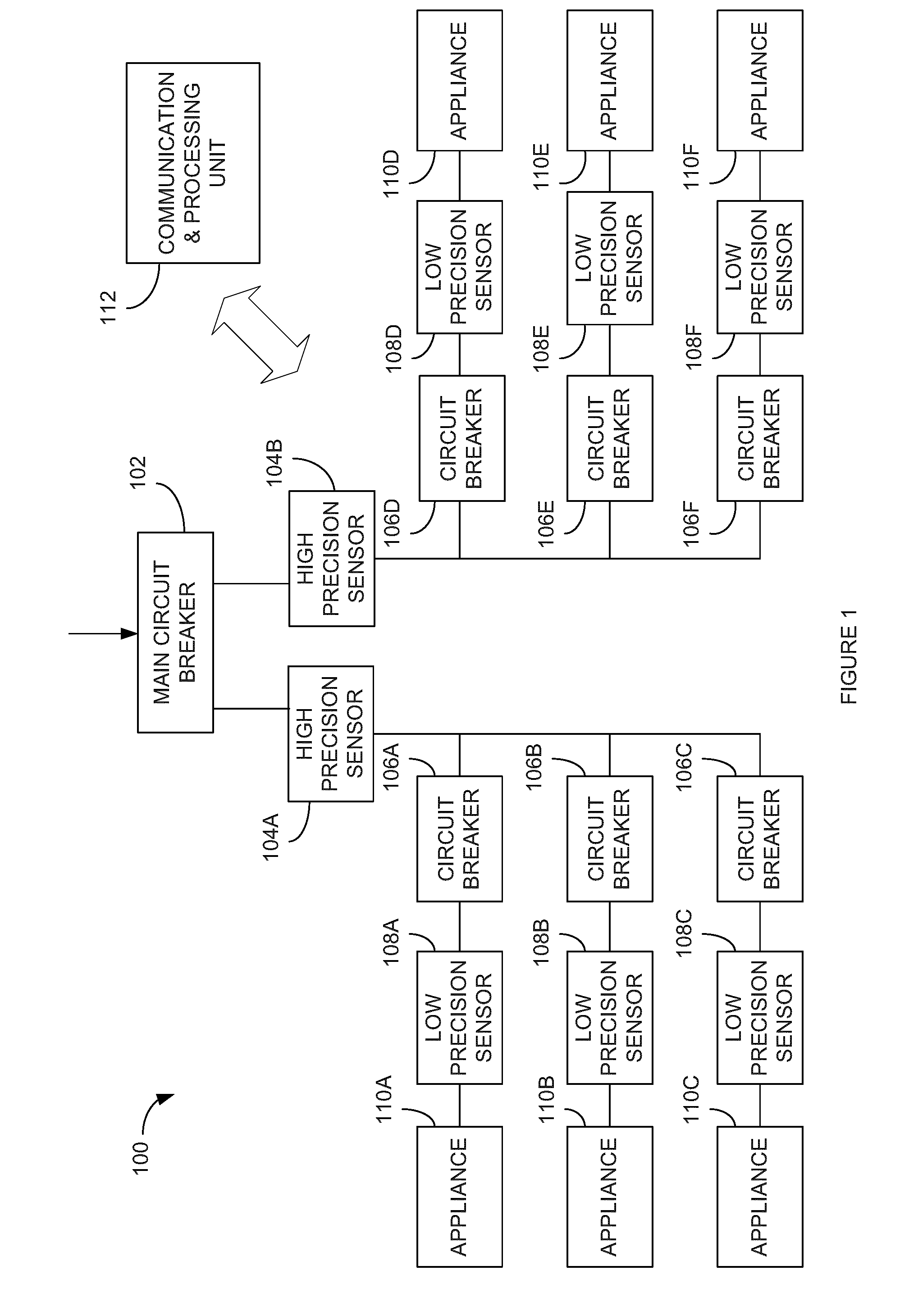
[0035]In a first embodiment, the auto-calibration algorithm comprises attributing the measure of the current sum to each circuit proportionally to the measure of each low precision sensor 108. For example, using:

İT: the precise measurement of the total current;

Î1, Î2, Î3: the low precision measurements of circuit breakers 1, 2 and 3;

[0036]The improved precision measurement of the current of each sensor is:

İ1=İT*Î1(Î1+Î2+Î3)

İ2=İT*Î2(Î1+Î2+Î3)

İ3=İT*Î3(Î1+Î2+Î3)

[0037]Using this technique, each individual low precision current measurement În can be calibrated to a more precise value.

second embodiment

[0038]In a second embodiment, the auto-calibration algorithm comprises summing waveforms provided by each sensor 108 for a given time window. Optimization techniques such as the Newton-Raphson technique, the bisection technique or the polynomial approximation technique may then be used to minimize the error, i.e. the difference between the computed sum and the precise measurement provided by sensors 104a, 104b, by adjusting a multiplicative gain for each signal provided by sensors 108. For example, using:

iT(t): the precise measurement of the total current;

Î1(t), Î2(t), Î3(t): the low precision measurements of circuit breakers 1, 2 and 3;

[0039]The following expression is computed:

e=İT(t)−(G1*Î1(t)+G2*Î2(t)+G3*Î3(t))

[0040]The parameter “e” may be minimized by adjusting G1, G2 and G3 using various optimization techniques. After convergence of the optimization algorithm, the precise measurement of each circuit is obtained by multiplying the measured current În(t) by its respective gain ...

third embodiment

[0041]In a third embodiment, mathematical correlation operations may be used to isolate each signal component from the precise sum. The correlation is calculated between each current signal from sensors 108 and the precise sum of currents provided by sensors 104a, 104b. Using this technique, the precise sum of current waveforms can be broken down into constituent signals corresponding to the current waveforms provided by low precision sensors 108. These constituent signals are attributed to each circuit based on the likelihood of the waveform. The error may thus be corrected, by the communication and processing unit 112 or a further processing unit (not shown), in order to increase precision of the measurements to be used for analysis.

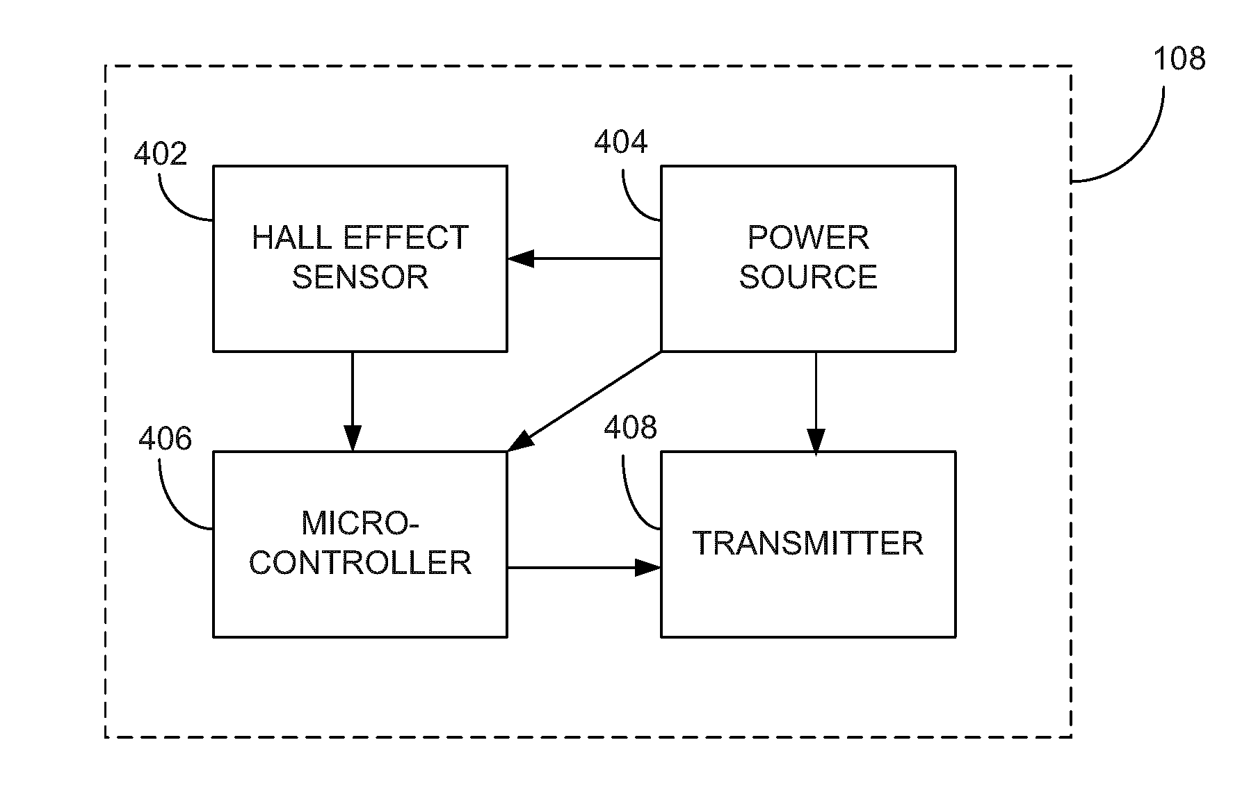
[0042]Other auto-calibration techniques known to those skilled in the art may be used in order to mitigate the effects of the sensitivity of the Hall effect sensors in the application as described.

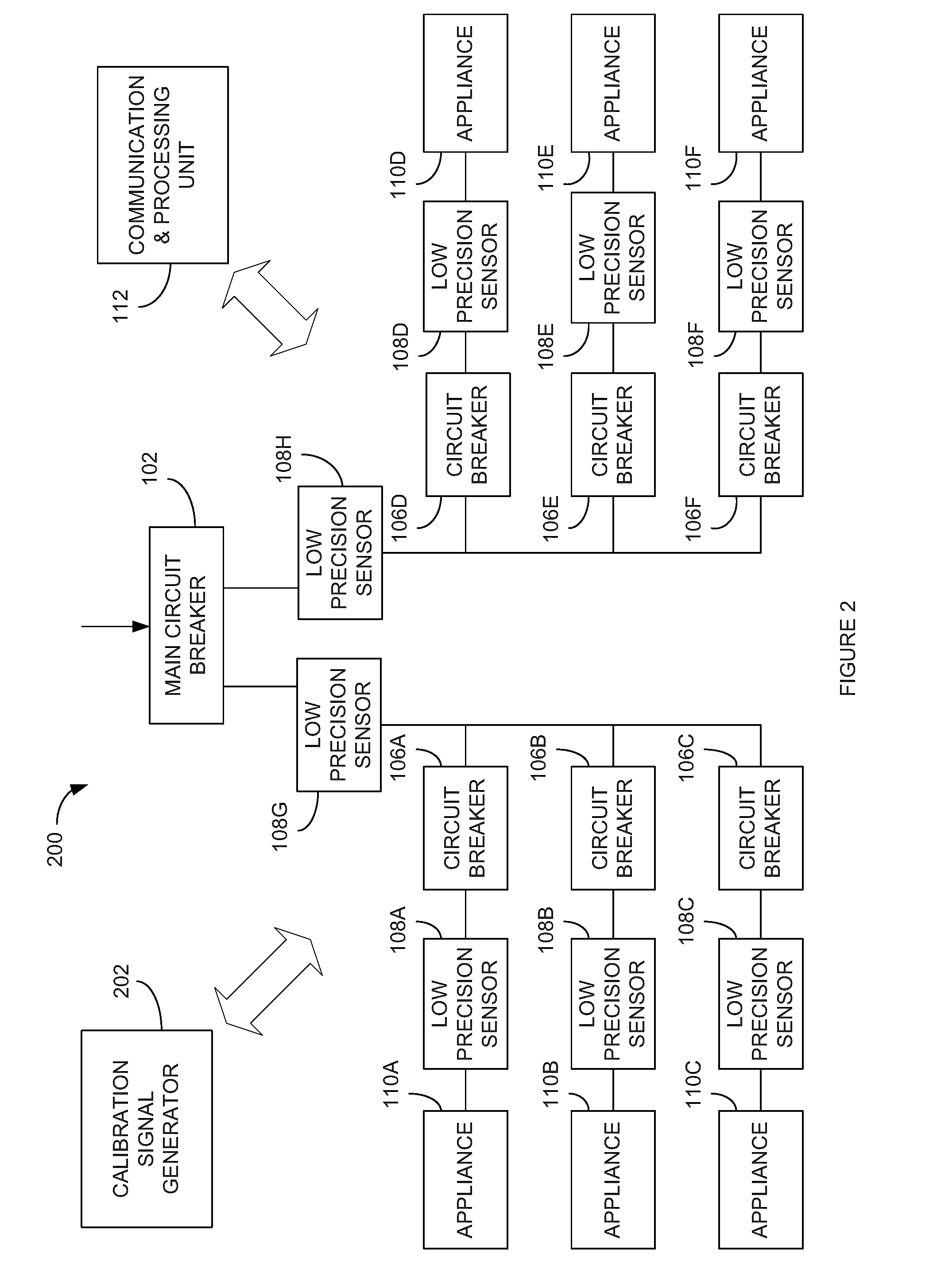
[0043]Referring to FIG. 2, there is illustrated an alte...


PUM


Abstract

There is described a system to measure the electrical consumption of a household. This system consists of a network of measuring devices that are attached to wires between electrical appliances and circuit breakers and of a communication and processing unit that receives measurement data from the measuring devices. Low precision sensors based on the Hall effect may be used for obtaining precise measurements of energy consumption by providing a casing for the measuring devices that ensures a fixed, known, and precise alignment with respect to the wire to which it is attached. Low precision sensors based on the Hall effect may also be used by performing a correction calibration of measured data.

Description

CROSS-REFERENCE TO RELATED APPLICATIONS[0001]This application claims priority under 35 U.S.C. 119(e) of U.S. Provisional Patent Application No. 61 / 639,355, filed on Apr. 27, 2012, the contents of which are hereby incorporated.TECHNICAL FIELD[0002]The present invention relates to the field of wireless sensors for residential electrical energy consumption measurements, and more particularly, to the use of low precision sensors based on the Hall effect.BACKGROUND OF THE ART[0003]By providing better information to users regarding energy consumption, better decisions may be made to assist in energy consumption reduction. There are already many products available on the market to measure the energy consumption of a residential environment. For example, The Energy Detective (TED) measures the total electricity consumption and provides real-time kW / hr readings, load profiles for up to 5 appliances, monthly bill projections, voltage and power factor. A current clamp is connected to the main ...

Claims


Application Information

Patent Timeline
Patent Type & Authority Applications(United States)
IPC IPC(8): G01R21/08
CPCG01R21/08G01R1/04G01R1/18G01R35/005G01R15/202G01R21/133H04L67/12H04L12/2823H04L2012/2841H04L2012/285Y04S20/242Y04S40/126Y04S40/18H02J13/00017H02J13/00026Y02B70/30Y02B90/20Y04S40/124Y04S20/20
Inventor GAGNON, GHYSLAINJOMPHE, SEBASTIENSICARD, DANIELDALLAIRE, MICHELARBOUR, DOMINIC
Owner POLYVALOR S E C
Why Eureka
Try Eureka