LED driving circuit, LED driving method, and liquid crystal display device

a driving circuit and led driving technology, applied in the direction of electric digital data processing, instruments, computing, etc., can solve the problems of voltage not being boosted up, affecting, and affecting the effect of the display quality

Active Publication Date: 2015-05-07
TIANMA MICRO ELECTRONICS CO LTD
View PDF4 Cites 12 Cited by
  • Summary
  • Abstract
  • Description
  • Claims
  • Application Information

AI Technical Summary

Benefits of technology

[0021]In order to achieve the foregoing object, the LED driving circuit according to the present invention is an LED driving circuit for controlling an LED circuit constituted with one LED or two or more LEDs, and the LED driving circuit employs a structure which includes: a duty ratio adjusting circuit unit which generates and outputs an adjusting signal for adjusting drive of the LED based on a PWM dimming signal inputted from outside; and a booster circuit unit which applies a driving voltage to the LED circuit according to the adjusting signal outputted from the duty ratio adjusting circuit unit, wherein the duty ratio adjusting circuit unit sets the adjusting signal to have a larger duty ratio than that of the PWM dimming signal inputted from outside within an adjusting period set from a point after a power is supplied to a point at which the LED circuit starts to connect electrically.
[0022]Further, the liquid crystal display device according to the present invention employs a structure which includes: a liquid crystal display panel which displays a video towards outside; a backlight which includes an LED circuit constituted with one LED or two or more LEDs and illuminates the liquid crystal panel from a back surface; and the LED driving circuit which drives the LED circuit by using a power supply voltage outputted from and the PWM dimming signal inputted from outside.
[0023]Furthermore, the video signal processing method according to the present invention is used with an LED driving circuit which includes a booster circuit unit which applies a driving voltage to an LED circuit constituted with one LED or two or more LEDs and a duty ratio adjusting circuit unit which generates and outputs an adjusting signal for adjusting drive of the LED circuit, and the method includes: inputting a PWM dimming signal used for controlling operations of the LED circuit from outside to the duty ratio adjusting circuit unit; generating and outputting the adjusting signal having a larger duty ratio than that of the PWM dimming signal by the duty ratio adjusting circuit unit within an adjusting period set in advance from a point after a power is supplied to a point at which the LED circuit starts to connect electrically; and applying a voltage by the booster circuit unit to the LED circuit according to the adjusting signal outputted from the duty ratio adjusting circuit unit.

Problems solved by technology

However, with this control circuit, when the duty of the PWM is low, the influence upon the characteristic of the driving circuit and the display quality becomes great since the operation period of the booster circuit is short.
However, the dimming circuit according to Patent Document 1 executes a prescribed boosting operation in an OFF period based on the reference voltage held in an ON period right before, so that the voltage of the ON period right before can be maintained in the OFF period but the voltage cannot be boosted up than that of the ON period right before.
That is, the boost-up time cannot be shortened greatly when it is desired to perform an operation for gradually increasing the anode voltage, e.g., when starting up the power source.
Thus, the circuit structure becomes complicated and large-scaled as the number of the LEDs is increased, so that it is difficult to use the circuit in common.
Further, the LED driving circuit is structured to supply the current even in a period where the LED is not lighted up, so that there is such an issue that the power is excessively consumed in the no light-up period.
In addition, there is a shift period in which the LED side and the detour route side (bypass side) are both in an ON state, so that there is a possibility of causing more excessive consumption of the power in the shift period.
Thus, there is a concern that flicker or the like may be visually recognized due to current ripple and voltage noise of the circuit generated at the time of switching or immediately after switching.
That is, there is a possibility of causing display quality deterioration.
However, as the LED driving circuit, it is inconvenient for a case where PWM is inputted as an external signal to change the duty ratio.

Method used


Image

  • LED driving circuit, LED driving method, and liquid crystal display device
  • LED driving circuit, LED driving method, and liquid crystal display device
  • LED driving circuit, LED driving method, and liquid crystal display device

Examples


first exemplary embodiment

[0036]A first exemplary embodiment of an LED driving circuit according to the present invention will be described by referring to FIG. 1 to FIG. 4.

(Overall Structures)

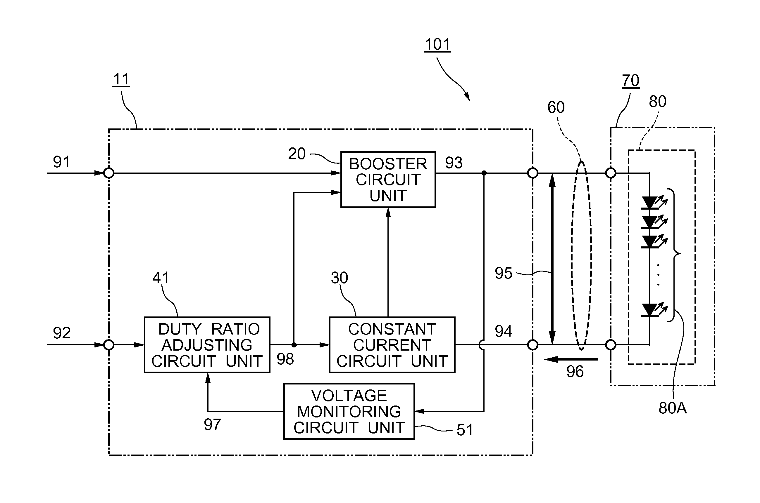
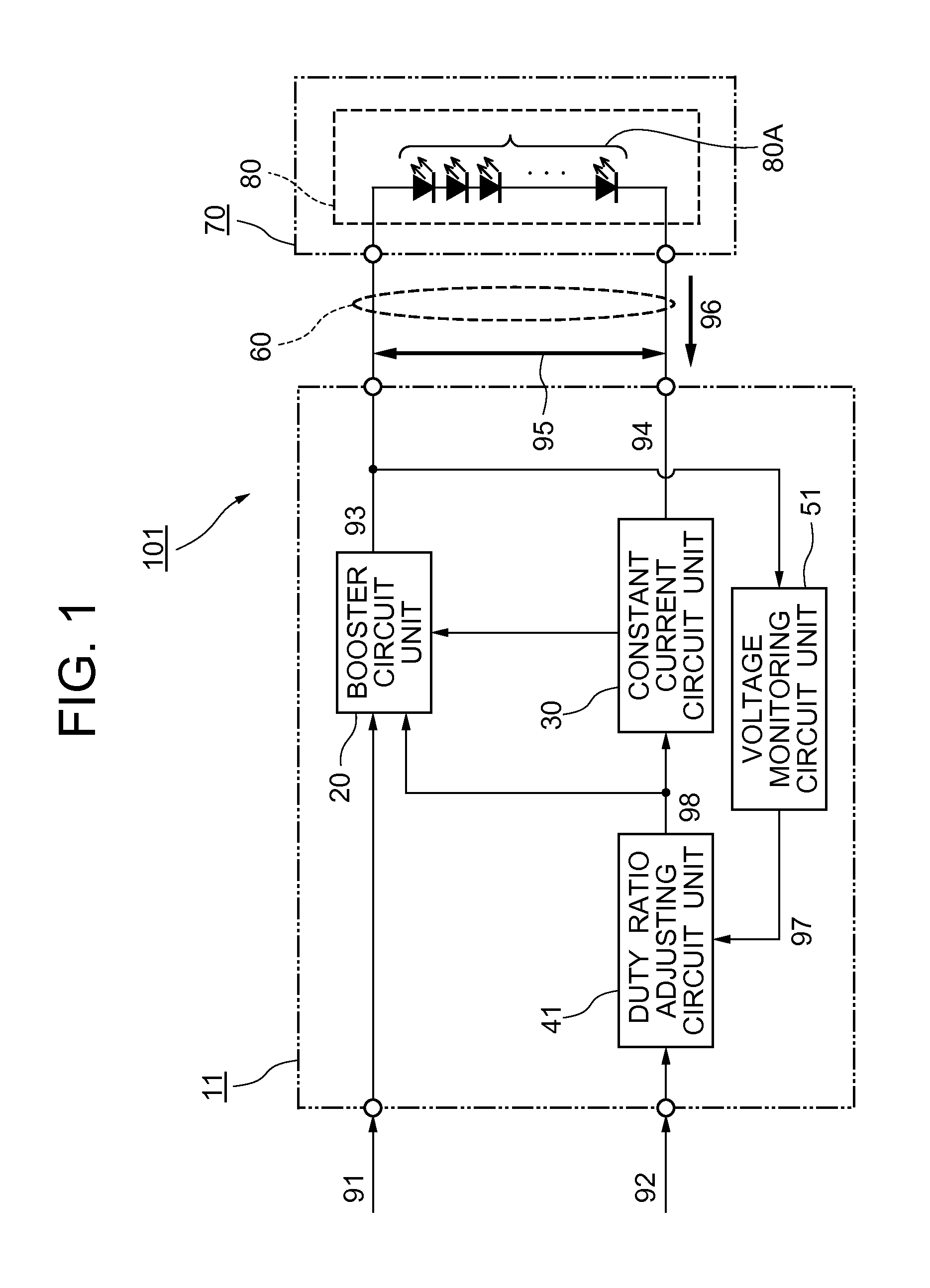
[0037]As shown in FIG. 1, an LED lighting device 101 provided to a liquid crystal display device (a video display device) according to the first exemplary embodiment includes: an LED backlight 70 which illuminates a display panel (not shown) such as a liquid crystal panel from the back surface; and an LED driving circuit 11 which performs driving controls regarding the LED backlight 70.

[0038]The LED backlight 70 shown in FIG. 1 includes an LED circuit 80 which is constituted by containing an LED group 80A in which a plurality of LEDs are connected in series.

As the LED group 80A, it is also possible to employ a structure in which two or more LEDs are connected in parallel, a structure in which a serial connection and a parallel connection are combined variously, etc. Understandably, it is also possible to employ a singl...

second exemplary embodiment

[0089]A second exemplary embodiment of the LED driving circuit and the LED lighting device 102 provided to the liquid crystal display device according to the present invention will be described by referring to FIG. 5 to FIG. 7. The same reference numerals are used for the structural members same as those of the above-described first exemplary embodiment.

(Overall Structures)

[0090]As shown in FIG. 5, an LED driving circuit 12 according to the second exemplary embodiment employs the structure that includes a current monitoring circuit unit 52 which monitors the LED current 96 (forward electric current) flown out from the cathode side of the LED circuit 80 of the first exemplary embodiment described above and transmits a signal (a second duty control signal 97B) based on the monitored current to a duty ratio adjusting circuit unit 42.

[0091]Further, for convenience, the signal transmitted by the voltage monitoring circuit unit 51 that is in the same structure as that of the first exempla...

third exemplary embodiment

[0114]A third exemplary embodiment of the LED driving circuit and the liquid crystal display device according to the present invention will be described by referring to FIG. 8 and FIG. 9. The same reference numerals are used for the structural members same as those of the above-described first and second exemplary embodiments.

(Overall Structures)

[0115]As shown in FIG. 8, the third exemplary embodiment employs an LED circuit 83 which includes two or more systems of LED groups constituted in such a manner that the anode voltage is used in common instead of the LED circuit 80 employed in the first and second exemplary embodiments described above. For convenience, FIG. 8 shows a case of providing two systems of LED groups.

[0116]As the LED group in this case, it is also possible to employ a structure in which a plurality of LEDs are connected in series or connected in parallel, a structure in which a serial connection and a parallel connection are combined variously, etc., as in the case...


PUM


Abstract

An LED driving circuit, an LED driving method, and a liquid crystal display device, which prevent deterioration of display quality by effectively shortening the time required for starting the LED backlight and stabilizing the driving operations are provided. The LED driving circuit for controlling an LED circuit constituted with one LED or two or more LEDs includes: a duty ratio adjusting circuit unit which generates/outputs adjusting signals for adjusting drive of the LED based on a PWM dimming signal inputted from outside; and a booster circuit unit which applies driving voltages to the LED circuit according to the adjusting signal outputted from the duty ratio adjusting circuit unit. The duty ratio adjusting circuit unit sets the adjusting signal to have a larger duty ratio than that of the PWM dimming signal within an adjusting period set after the power is supplied until the LED circuit starts to connect electrically.

Description

CROSS-REFERENCE TO RELATED APPLICATION[0001]This application is based upon and claims the benefit of priority from Japanese patent application No. 2013-228789, filed on Nov. 1, 2013, the disclosure of which is incorporated herein in its entirety by reference.BACKGROUND OF THE INVENTION[0002]1. Field of the Invention[0003]The present invention relates to a driving control technique for a backlight that is provided to a liquid crystal display device or the like. More specifically, the present invention relates to an LED driving circuit for adjusting operations of an LED backlight, an LED driving method, and a liquid crystal display device.[0004]2. Description of the Related Art[0005]Recently, as an LCD (Liquid Crystal Display) backlight, an LED (Light Emitting Diode) has been used broadly from the viewpoints of long life, low power consumption, and reduction in the load on the environments (mercury free).[0006]With an LED driving circuit on which the LED is mounted, generally known is...

Claims


Application Information

Patent Timeline
Patent Type & Authority Applications(United States)
IPC IPC(8): G09G3/34G09G3/36
CPCG09G3/3406G09G2320/0626G09G3/3648
Inventor MIO, SETSUKO
Owner TIANMA MICRO ELECTRONICS CO LTD
Why Eureka
Try Eureka