
Camera for vehicle vision system

Active Publication Date: 2015-05-07
MAGNA ELECTRONICS
View PDF2 Cites 71 Cited by
  • Summary
  • Abstract
  • Description
  • Claims
  • Application Information

AI Technical Summary

Benefits of technology

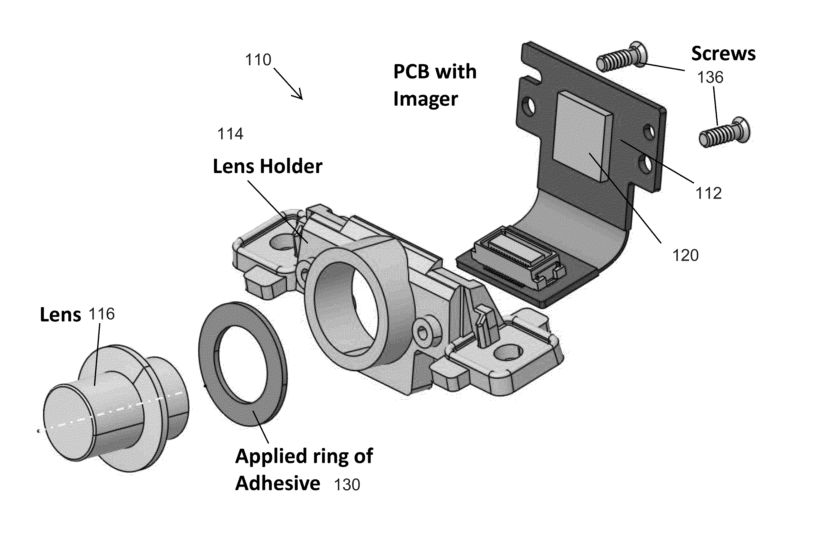
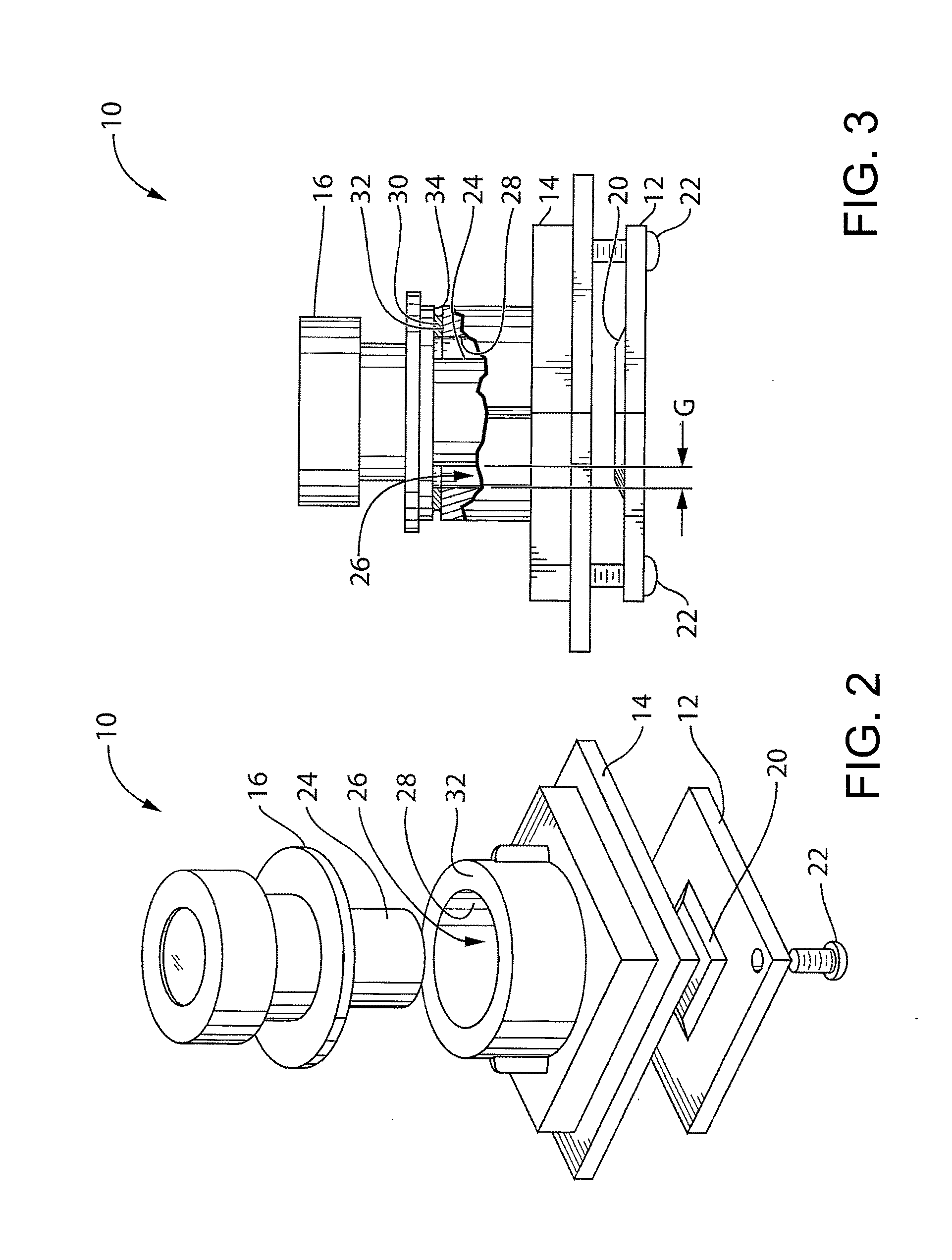
The present invention provides an improved camera assembly for vehicles that uses an adhesive to attach the lens to the imager. This adhesive is strong and stable, resistant to environmental factors like sun and rain. The adhesive is first exposed to UV light to reach an initial curing strength, and then further exposed to UV light to reach a further curing strength. This results in a better bond between the lens and the imager, improving the overall performance of the camera assembly.

Problems solved by technology

For example, if the lens is positioned such that the video input is not in focus, then the video information passed to the driver may be blurry, and other vehicular systems, such as a collision detection system for example, may not function as well as they otherwise could.

Method used


Image

  • Camera for vehicle vision system
  • Camera for vehicle vision system
  • Camera for vehicle vision system

Examples


Embodiment Construction

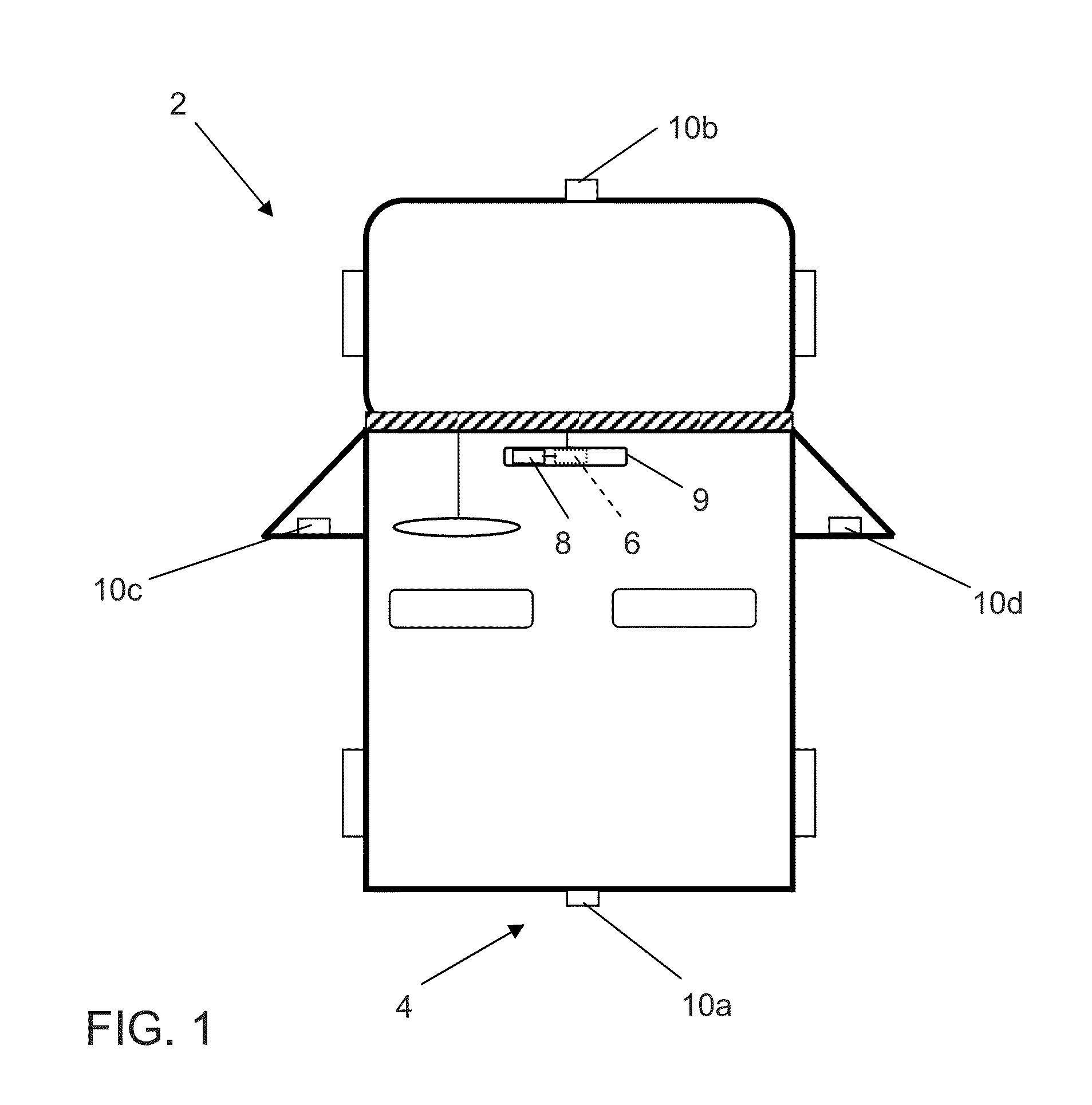
[0020]A vehicle vision system and / or driver assist system and / or object detection system and / or alert system operates to capture images exterior of the vehicle and may process the captured image data to display images and to detect objects at or near the vehicle and in the predicted path of the vehicle, such as to assist a driver of the vehicle in maneuvering the vehicle in a rearward direction. The vision system includes an image processor or image processing system that is operable to receive image data from one or more cameras and provide an output to a display device for displaying images representative of the captured image data. Optionally, the vision system may provide a top down or bird's eye or surround view display and may provide a displayed image that is representative of the subject vehicle, and optionally with the displayed image being customized to at least partially correspond to the actual subject vehicle.

[0021]Referring now to the drawings and the illustrative embo...


PUM

PropertyMeasurementUnit
Temperatureaaaaaaaaaa
Fractionaaaaaaaaaa
Timeaaaaaaaaaa

Abstract

A vehicular camera includes a lens, a printed circuit board and an imager. The lens has a plurality of optical element and is disposed at a lens holder. The imager is disposed at the printed circuit board. The adhesive is initially curable in an initial radiation curing process that comprises exposure to UV light, and initially-cured adhesive is further curable to a further cured strength in a secondary thermal curing process. The adhesive is initially cured via the initial radiation curing process after the lens is brought into focus with the imager and is optically center-aligned therewith. The initially-cured adhesive, as cured via the initial radiation curing process, holds the lens optically center-aligned and in focus with the imager. After the initial radiation curing process, the lens holder, adhesively attached to one of the printed circuit board and the holding element, is moved to the secondary thermal curing process.

Description

CROSS REFERENCE TO RELATED APPLICATIONS[0001]The present application claims the filing benefits of U.S. provisional application Ser. No. 61 / 905,462, filed Nov. 18, 2013 and Ser. No. 61 / 901,127, filed Nov. 7, 2013, which are hereby incorporated herein by reference in their entireties.FIELD OF THE INVENTION[0002]The present invention relates generally to vehicle vision systems and, more particularly, to vehicular cameras for vehicle vision systems.BACKGROUND OF THE INVENTION[0003]Vehicular cameras are used for a variety of purposes, such as to assist a driver in avoiding obstacles behind a vehicle when backing up, and to detect imminent collisions ahead of the vehicle when driving forward. A vehicular camera includes a lens that focuses video input on an image sensor provided on an imager. In general, the position of the lens relative to the image sensor can impact the quality of the video input received by the image sensor. For example, if the lens is positioned such that the video i...

Claims


Application Information

Patent Timeline
IPC IPC(8): H04N5/225C09J163/00B60R1/00
CPCH04N5/2254B60R2300/10C09J163/00B60R1/00H04N23/55H04N23/54H04N23/51C09J5/00C09J2463/00
Inventor WINDEN, BRIAN J.DEVOTA, ROBERT A.SESTI, MATTHEW C.STEMMER, JOSEPH A.BYRNE, STEVEN V.GARCIA, JOHN R.OLSON, DAVID F.
Owner MAGNA ELECTRONICS
Learn More