Very low inductance flexible electrical connector insert

Active Publication Date: 2015-05-07
QUELL CORP
View PDF15 Cites 7 Cited by
  • Summary
  • Abstract
  • Description
  • Claims
  • Application Information

AI Technical Summary

Benefits of technology

[0009]The present invention is of a connector insert comprising one or more layers of conductive elastomer. Preferably, the layers have a volume resistivity less than about 0.010 ohms/cm. The insert can be placeable into an existing connector. The layers have holes for pins of the connector, and provide at least a connector shell contact, a ground plane, and a pin contact. The connector insert can additionally co

Problems solved by technology

The circuit board technology corrupts the existing environmental seal of the connector, and so is unsuitable for high-reliability connectors.
However, the filament wire interconnects within the insert introduce unwanted stray

Method used


Image

  • Very low inductance flexible electrical connector insert
  • Very low inductance flexible electrical connector insert
  • Very low inductance flexible electrical connector insert

Examples


Embodiment Construction

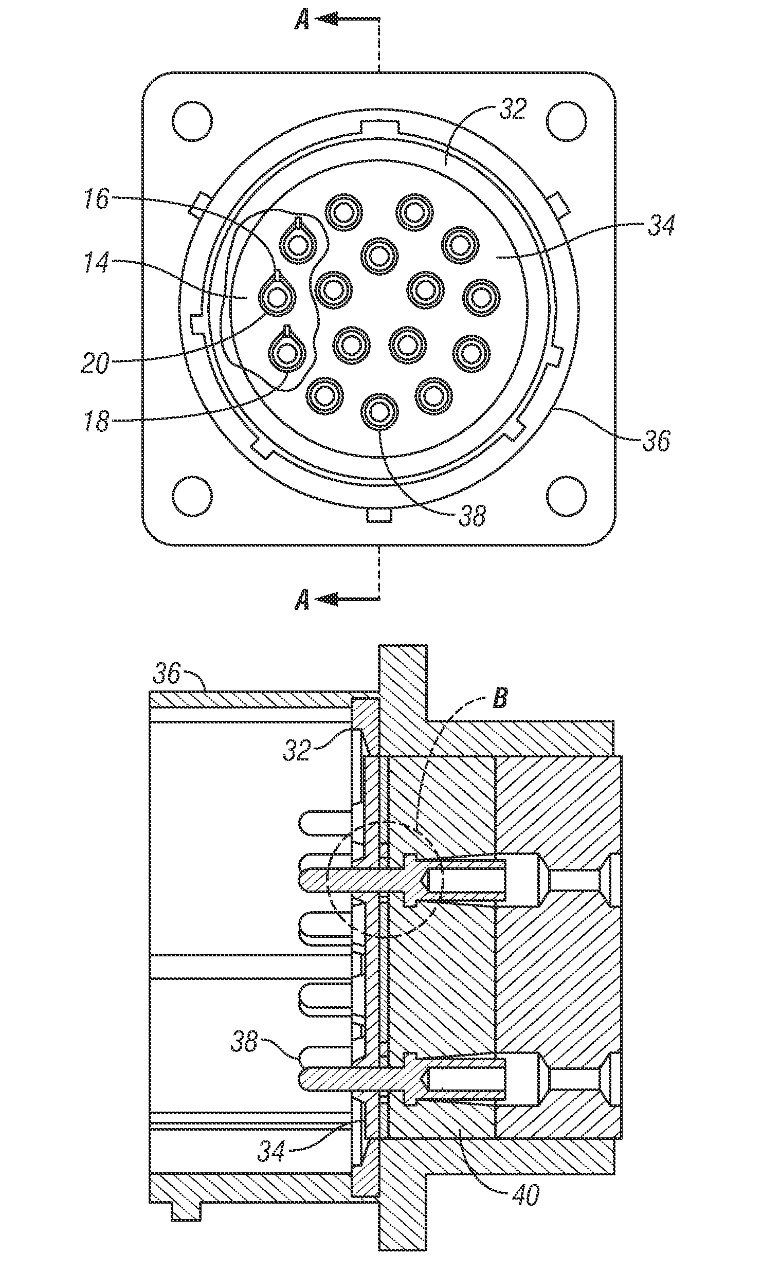
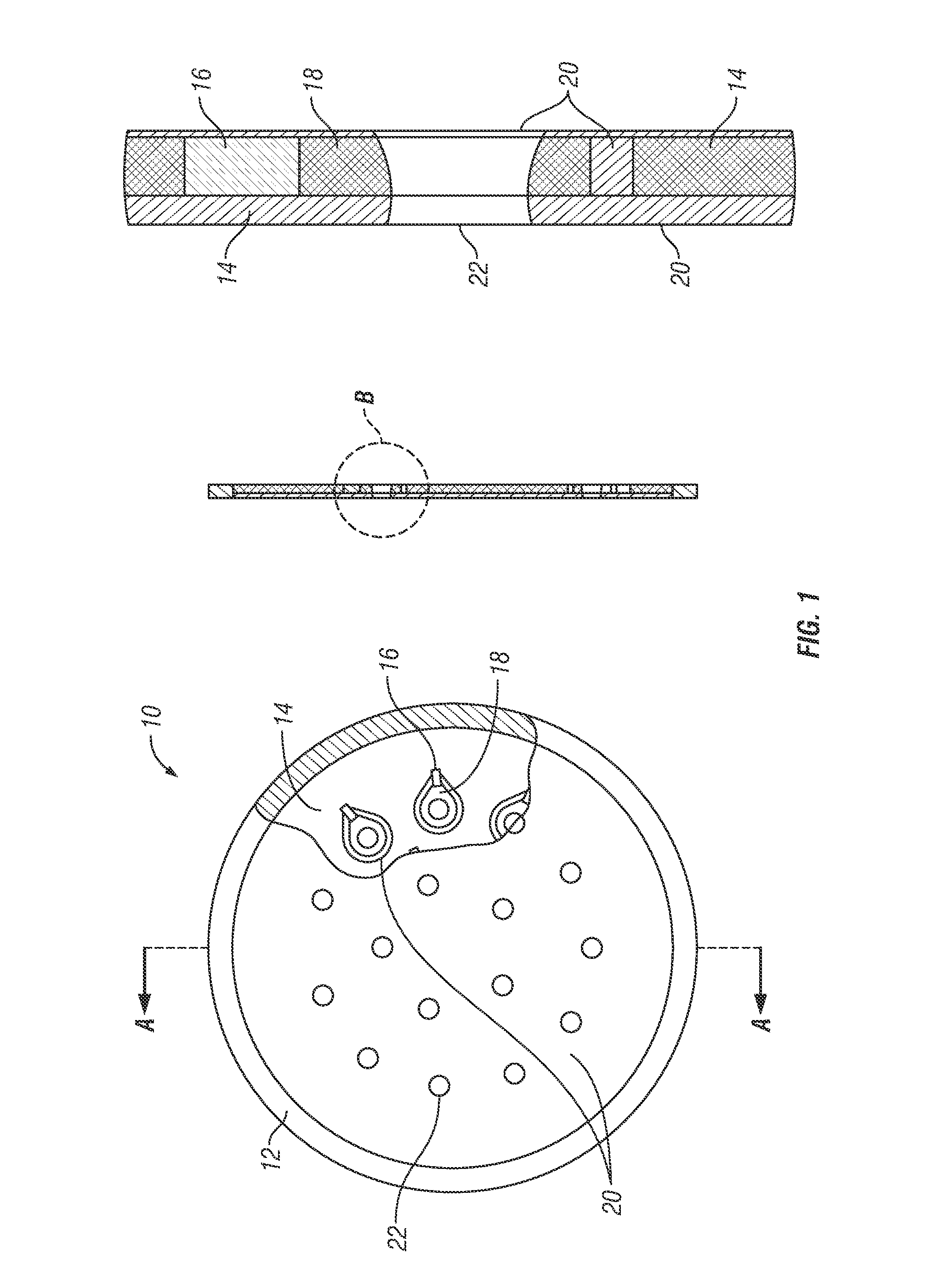
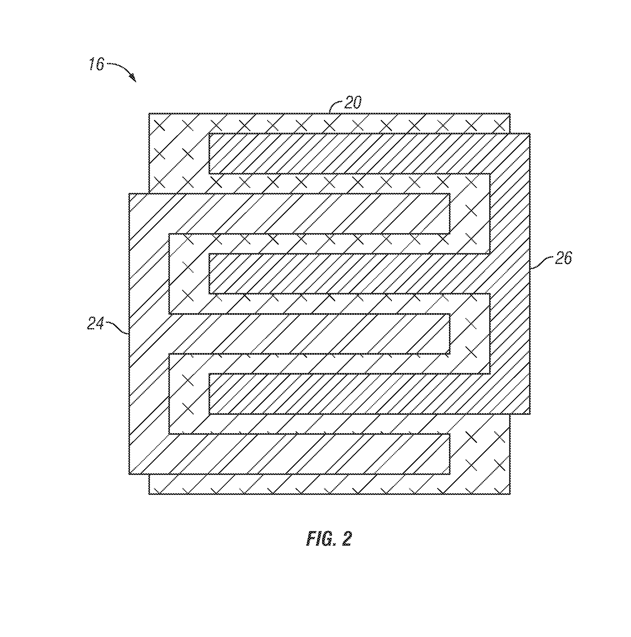
[0020]The present invention employs planar conductive layers rather than the wire interconnects within a connector insert, which provides a number of advantages. The conductive layers can be conductive elastomer or other conductive element(s) such as a thin metal sheet, but the preferred construct is conductive silicone elastomer, with a volume resistivity preferably less than about 0.010 ohms / cm. Electrically opposing conductive layers are insulated from each other by the non-conductive elastomer. A surface mount device, such as a 0402 sized capacitor, transient voltage suppressor, or resistor, is connected between the two conductive layers. This planar arrangement of the conductors greatly reduces unwanted stray inductance. Further, a small capacitor can be formed by overlapping the opposing conductors and separating them with a thin layer of non-conductive elastomer, or other non-conductive material with high dielectric constant, such as polypropylene. A relative permittivity gre...


PUM

PropertyMeasurementUnit
Resistance per lengthaaaaaaaaaa
Electrical conductoraaaaaaaaaa
Electrical resistivityaaaaaaaaaa

Abstract

A connector insert comprising a plurality of layers of conductive elastomer, and a concomitant method of employing a connector insert, the method comprising the steps of fabricating a plurality of layers of conductive elastomer as an insert and placing the insert into a connector.

Description

CROSS-REFERENCE TO RELATED APPLICATIONS[0001]This application claims priority to and the benefit of the filing of U.S. Provisional Patent Application Ser. No. 61 / 898,927, entitled “Very Low Inductance Design for Electrical Connector Insert”, filed on Nov. 1, 2013, and the specification and claims thereof are incorporated herein by reference.STATEMENT REGARDING FEDERALLY SPONSORED RESEARCH OR DEVELOPMENT[0002]Not Applicable.INCORPORATION BY REFERENCE OF MATERIAL SUBMITTED ON A COMPACT DISC[0003]Not Applicable.COPYRIGHTED MATERIAL[0004]Not Applicable.BACKGROUND OF THE INVENTION[0005]1. Field of the Invention (Technical Field)[0006]The present invention relates to inserts installed into an existing or new electrical connector to reliably add electrical circuitry to the system and concomitant methods of use and construction.[0007]2. Description of Related Art[0008]The present invention primarily relates to an insert installed into an existing or new electrical connector to reliably add ...

Claims


Application Information

Patent Timeline
IPC IPC(8): H01R13/24H01G4/002H01R43/00H01R27/00
CPCH01R13/2414H01R43/00H01G4/002H01R27/00H01R13/6464H01R13/6588H01R13/6599H01R13/6625H01R2107/00Y10T29/49208H01R13/7195
Inventor GODANA, KENERVEN, DUSTYFOREMAN, KEVINMILLER, PAUL
Owner QUELL CORP
Why Eureka
Try Eureka