Systems and methods of adjusting a rotating gantry system

a rotating gantry and gantry technology, applied in the direction of rotary bearings, shafts and bearings, therapy, etc., can solve the problems of time-consuming and complicated, patient movement to compensate for beam misalignment, and the time it takes to construct and implement a working system

Active Publication Date: 2015-05-07
PRONOVA SOLUTIONS
View PDF1 Cites 18 Cited by
  • Summary
  • Abstract
  • Description
  • Claims
  • Application Information

AI Technical Summary

Benefits of technology

[0024]Example embodiments of the present general inventive concept may also be achieved by providing a system to adjust a gantry apparatus of a proton treatment system, including a gantry to carry a proton beam nozzle, the proton beam nozzle being configured to emit a proton beam to an isocenter of the gantry, one or more adjustable members spaced apart about a circumference of the gantry to

Problems solved by technology

One of the challenges facing PT systems is to maintain proper alignment between the proton delivery nozzle and the isocenter of the rotating gantry system when the gantry is rotated to different treatment angles.
However, moving the patient to compensate for beam misalignment can become quite time consuming and complicated, especially if

Method used


Image

  • Systems and methods of adjusting a rotating gantry system
  • Systems and methods of adjusting a rotating gantry system
  • Systems and methods of adjusting a rotating gantry system

Examples


Embodiment Construction

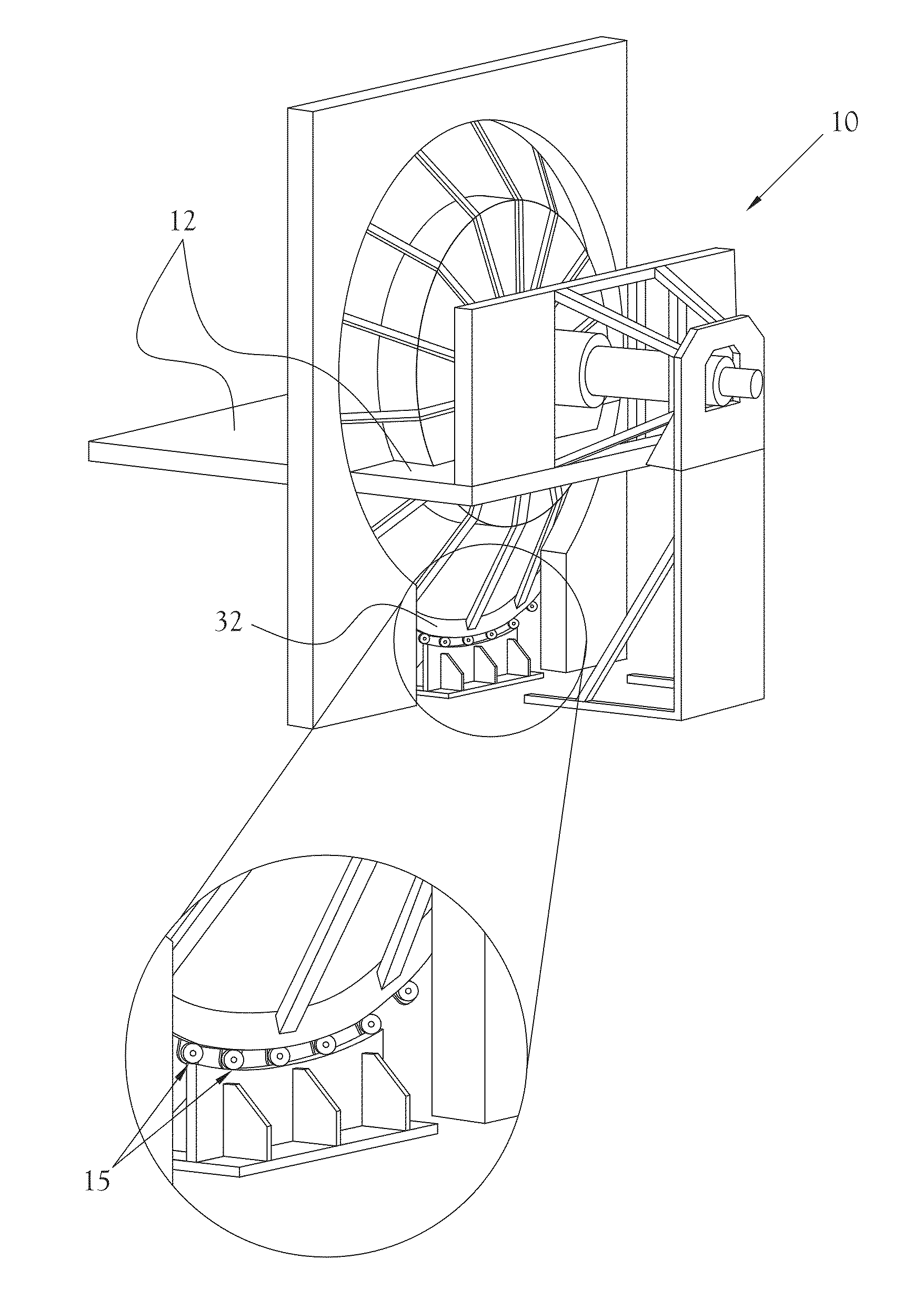
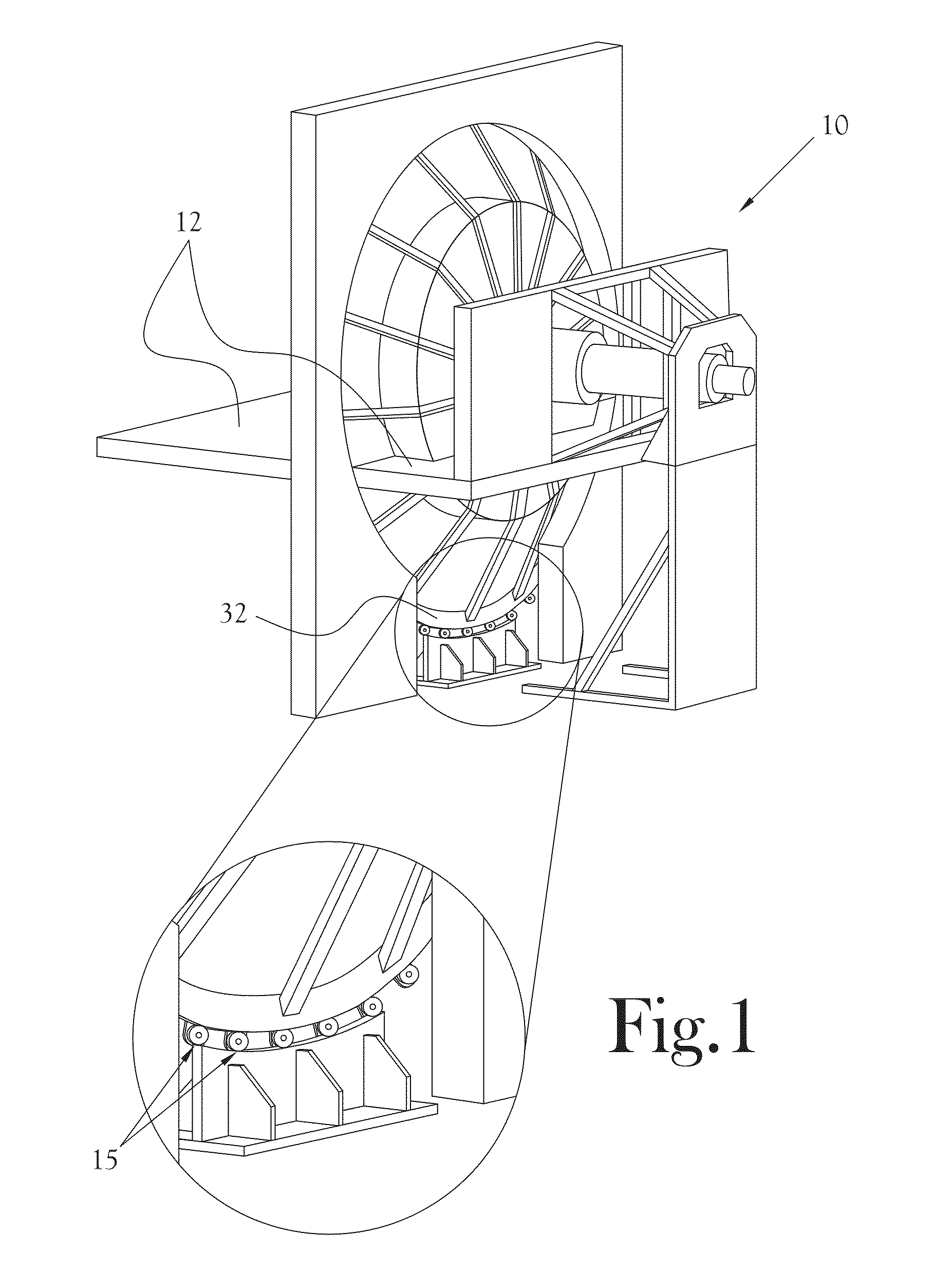
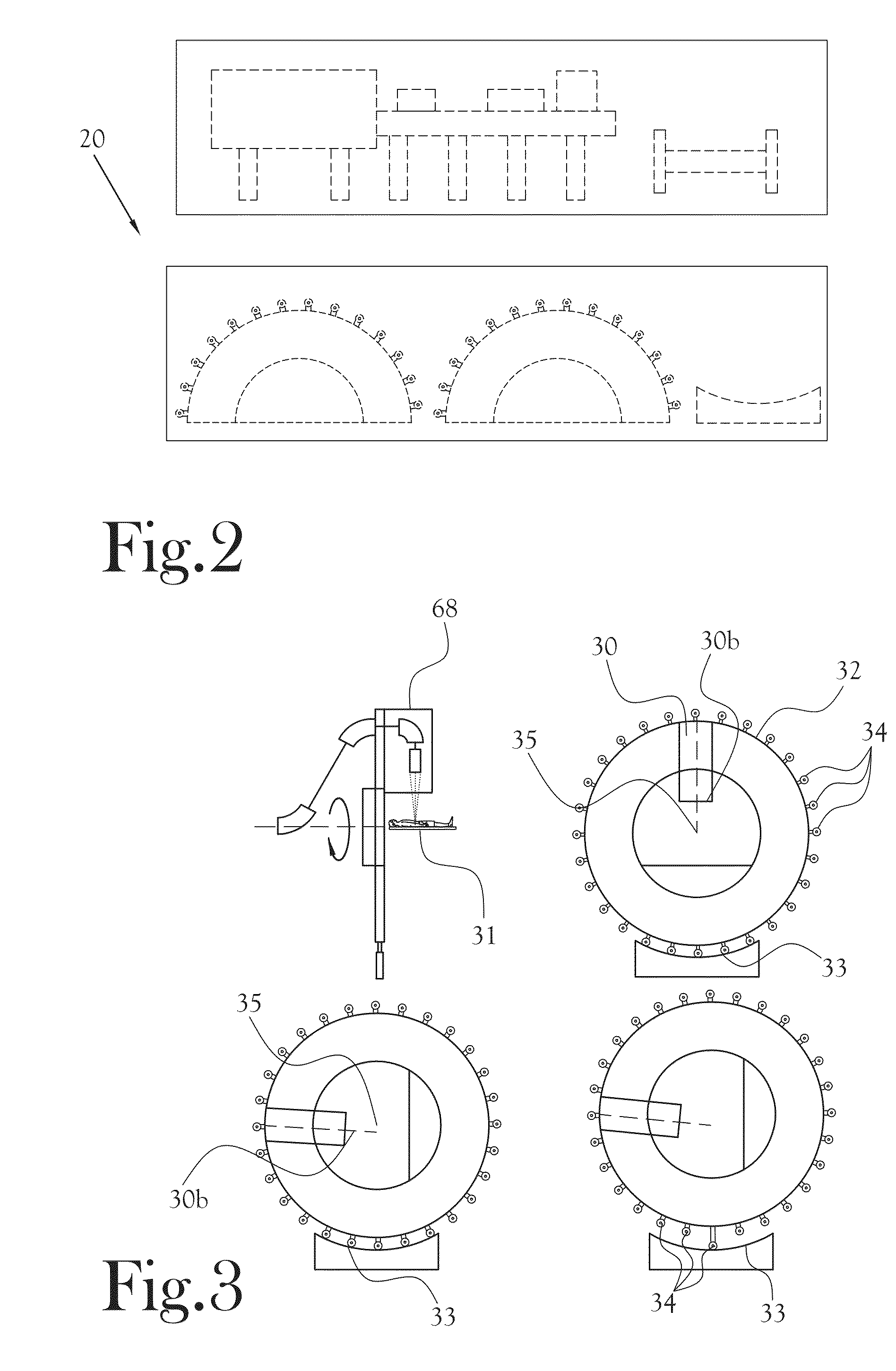
[0084]Reference will now be made to the example embodiments of the present general inventive concept, examples of which are illustrated in the accompanying drawings and illustrations. The example embodiments are described herein in order to explain the present general inventive concept by referring to the figures.

[0085]The following detailed description is provided to assist the reader in gaining a comprehensive understanding of the methods, apparatuses, and / or systems described herein. Accordingly, various changes, modifications, and equivalents of the methods, apparatuses, and / or systems described herein will be suggested to those of ordinary skill in the art. The described progression of any processing operations described are merely examples, however, and the sequence of operations is not limited to that set forth herein and may be changed as is known in the art, with the exception of operations necessarily occurring in a certain order. Also, description of well-known functions ...


PUM

PropertyMeasurementUnit
Angleaaaaaaaaaa
Angleaaaaaaaaaa
Weightaaaaaaaaaa

Abstract

A gantry wheel adjustment system and method to adjust a gantry wheel of a proton treatment system, including an estimation unit to estimate a bearing adjustment value for each of the adjustable bearings based on a stiffness parameter of each adjustable bearing, the stiffness parameter being a function of a force applied at each adjustable bearing and a deflection of the gantry wheel associated with the force applied at each adjustable bearing, the bearing adjustment value corresponding to a nominal position value for each adjustable bearing to compensate for gantry wheel flexing when the gantry wheel is rotated from a first angular position to a second angular position, the adjustable bearings being configured to support the gantry wheel on the bearing surface and maintain the proton beam at the isocenter of the gantry wheel during gantry wheel rotation.

Description

CROSS-REFERENCE TO RELATED APPLICATIONS[0001]This application is a Continuation-In-Part of U.S. application Ser. No. 14 / 064,732, filed on Oct. 28, 2013, which claims priority from U.S. Provisional Application Nos. 61 / 719,129, filed on Oct. 26, 2012, and 61 / 880,605, filed on Sep. 20, 2013, the disclosures of which are incorporated by reference herein.FIELD OF INVENTION[0002]The present general inventive concept relates to a rotating gantry system, and more particularly, to systems and methods of adjusting a rotating gantry system to maintain alignment of ae proton delivery mechanism with respect to the gantry's axis of rotation for proton therapy.BACKGROUND[0003]Proton Therapy (PT) is a cancer treatment technology that uses high energy protons to penetrate a patient's body and deposit energy into treatment areas such as cancerous tumors. PT systems commonly implement a rotating gantry wheel that directs the proton beam to the patient from any angle between zero and 360 degrees. This ...

Claims


Application Information

Patent Timeline
IPC IPC(8): A61N5/10F16C19/54
CPCA61N5/1081A61N2005/1087F16C19/54Y10T29/49826
Inventor MATTEO, JOSEPH C.HUBER, JONATHANHANSEN, PETER
Owner PRONOVA SOLUTIONS
Why Eureka
Try Eureka