Rotational atherectomy device with exchangeable drive shaft and meshing gears

a technology of rotating atherectomy and drive shaft, which is applied in the field of rotational atherectomy devices with exchangeable drive shafts and meshing gears, can solve the problems of requiring relatively intricate manipulation of very small components, steps required to actually disconnect the exchangeable portion of the drive shaft, and affecting the recovery of patients,

Active Publication Date: 2015-05-07
CARDIOVASCULAR SYST INC
View PDF2 Cites 7 Cited by
  • Summary
  • Abstract
  • Description
  • Claims
  • Application Information

AI Technical Summary

Benefits of technology

[0024]In some embodiments of the device, the first connector is a pivoting connector having complementary first and second sections, wherein the first section is integrally formed with the distal section of the handle, and the complementary second section is integrally formed with the drive shaft cartridge. In certain embodiments, the second connector includes complementary first and second sections, wherein the first section is integrally formed with the handle, and the second section is integrally formed with the proximal section of the drive shaft cartridge. Removably connecting the handle and the drive shaft cartridge using the second connector removably meshes the prime mover gear and the drive shaft gear, such that a rotational movement of one of the prime mover and the drive shaft induces a rotational movement in the other.

Problems solved by technology

If left untreated, such stenoses can cause angina, hypertension, myocardial infarction, strokes and the like.
While the Rotalink System® does permit one to change the burr size, the steps required to actually disconnect the exchangeable portion of the drive shaft and replace it with another exchangeable portion of the drive shaft are quite involved and require relatively intricate manipulation of very small components.
While this system does permit one to exchange one size burr (together with a portion of the drive shaft) for a burr of another size, the exchange procedure is not an easy one and must be performed with considerable care.
Surgical gloves diminish the tactile sensations of the individual performing the exchange procedure and therefore make such exchange procedure even more difficult.

Method used


Image

  • Rotational atherectomy device with exchangeable drive shaft and meshing gears
  • Rotational atherectomy device with exchangeable drive shaft and meshing gears
  • Rotational atherectomy device with exchangeable drive shaft and meshing gears

Examples


Embodiment Construction

[0050]In the following detailed description of the various embodiments illustrated in the appended figures, like components and elements are identified using like reference numerals.

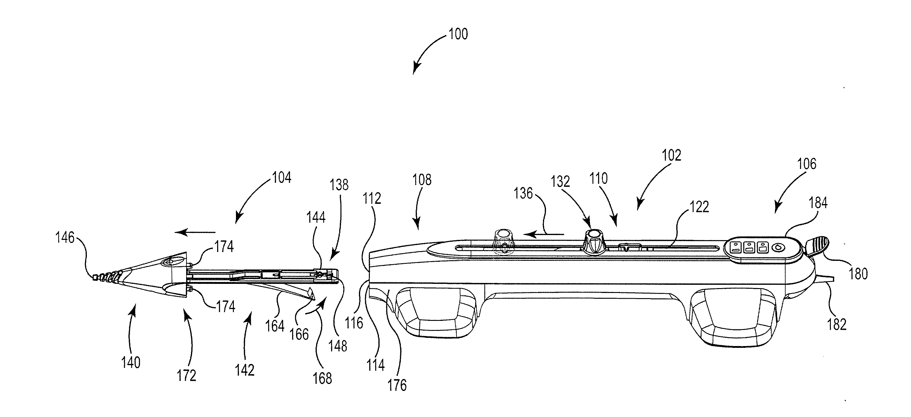
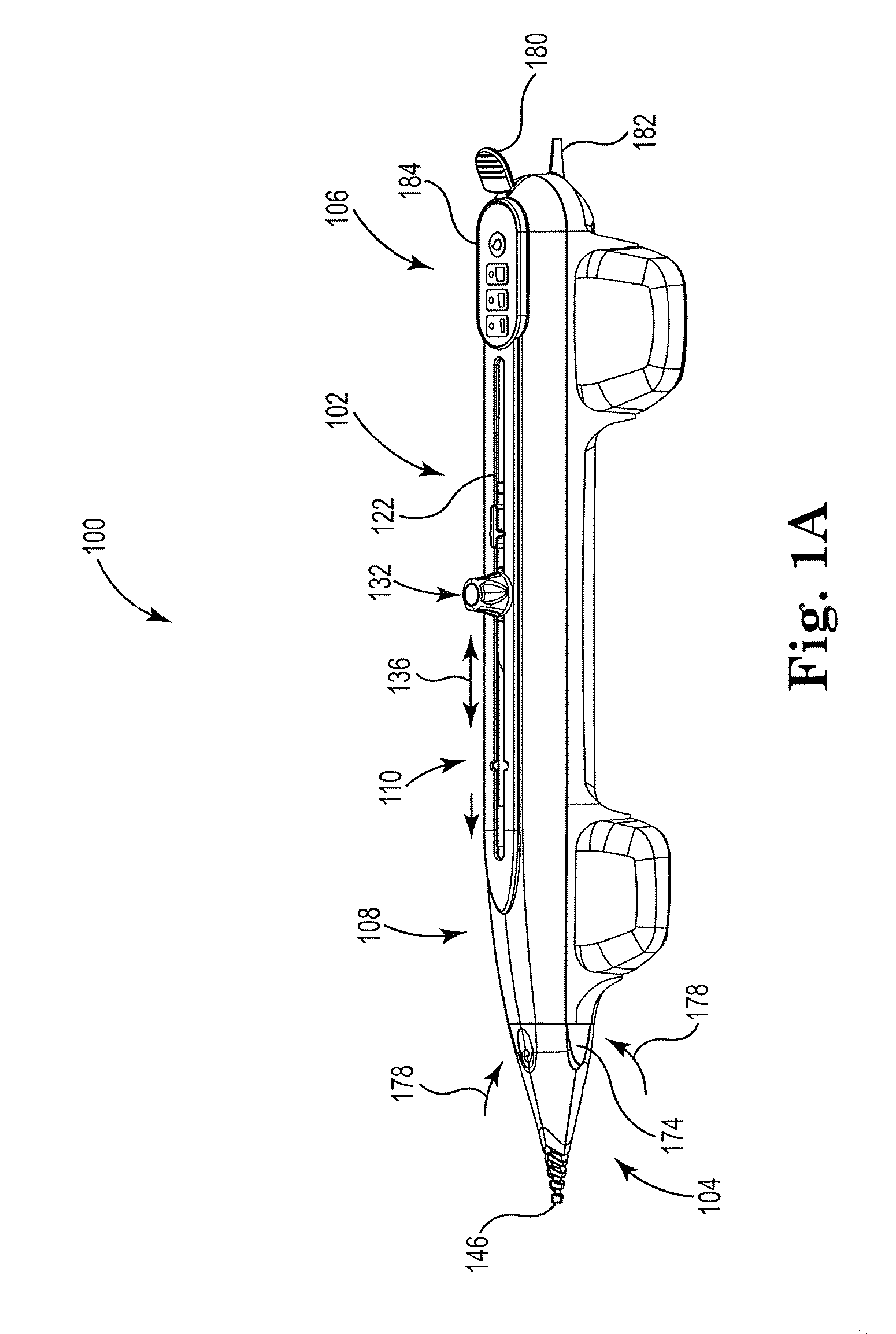
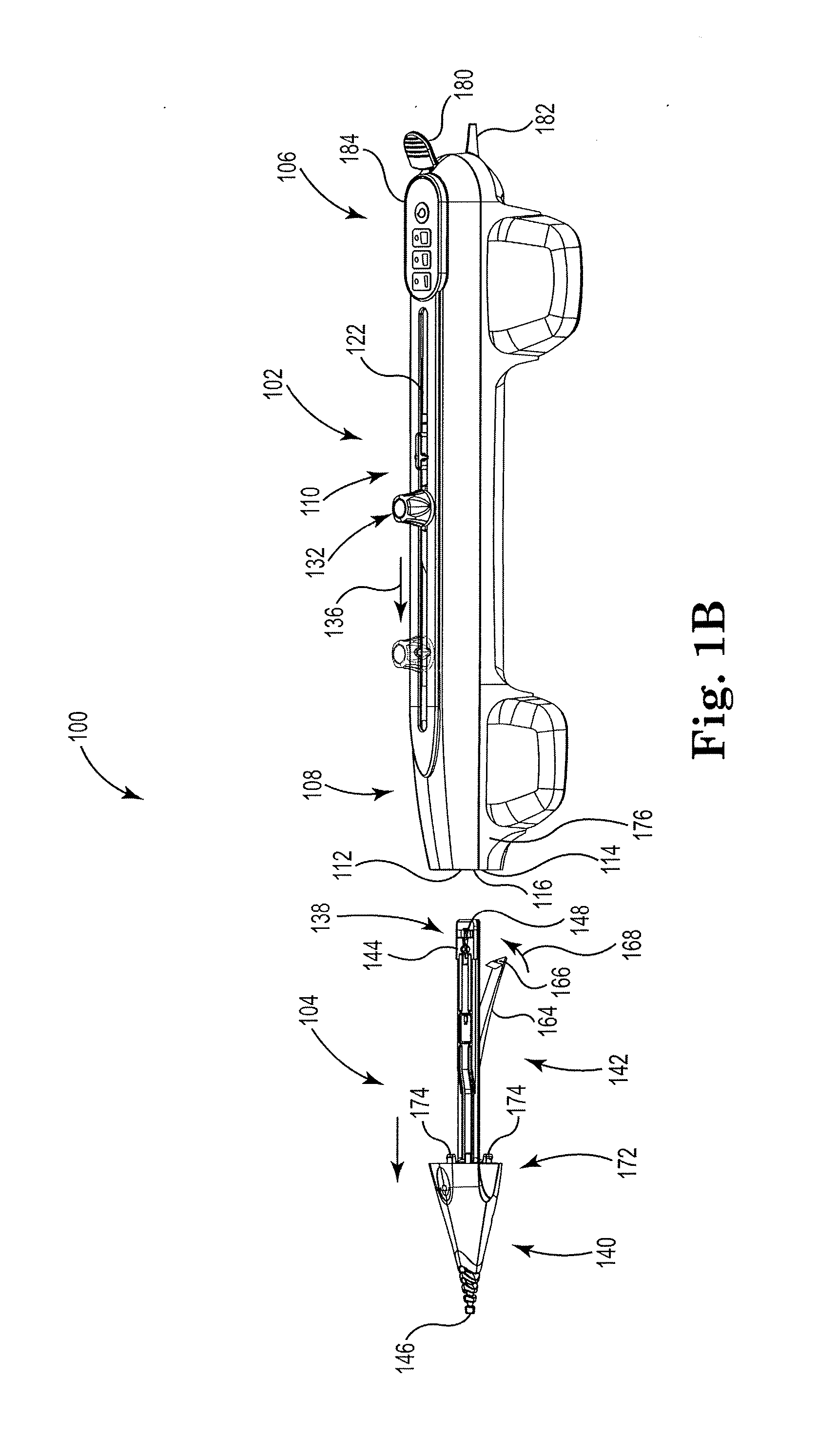
[0051]FIGS. 1A and 1B, respectively, are perspective views of an embodiment of a rotational atherectomy device 100 in a “loaded” and an “unloaded” state, and FIG. 1C is a longitudinal cross-sectional view the device 100 in the “loaded” state. The device 100 includes a handle 102 and an exchangeable drive shaft cartridge 104 that can be removably connected to one another. The device 100 is considered to be in the “loaded” state when the handle 102 and the drive shaft cartridge 104 are connected to one another, and is considered to be in the “unloaded” state when the handle 102 and the drive shaft cartridge 104 are separated from one another. The drive shaft cartridge 104 is referenced as “exchangeable” because the device 100 is configured for enabling an operator to use different drive shaft cartridges wi...


PUM

PropertyMeasurementUnit
diameteraaaaaaaaaa
distanceaaaaaaaaaa
displacementaaaaaaaaaa

Abstract

An atherectomy device with an exchangeable drive shaft is disclosed, having a drive shaft gear at a distal end of the exchangeable drive shaft for meshing engagement with a prime mover gear on the output shaft of the prime mover. The exchangeable drive shaft is inserted into an opening at the distal end of the handle housing and moved axially in a proximal direction. Surface features on at least the prime mover housing and the engageable drive shaft help to align the drive shaft gear with the prime mover gear for meshing engagement.

Description

CROSS-REFERENCE TO RELATED APPLICATIONS[0001]This application is a continuation-in-part of U.S. patent application Ser. No. 14 / 492,683 filed Sep. 22, 2014, which is a divisional of U.S. patent application Ser. No. 14 / 340,353 filed Jul. 24, 2014, which claims the benefit of U.S. Provisional Application No. 61 / 950,402, filed Mar. 10, 2014, and the benefit of U.S. Provisional Application No. 61 / 858,345 filed Jul. 25, 2013, the entirety of which prior filed applications are hereby incorporated by reference.STATEMENT REGARDING FEDERALLY SPONSORED RESEARCH OR DEVELOPMENT[0002]Not ApplicableBACKGROUND OF THE INVENTION[0003]1. Field of the Invention[0004]The disclosure relates to devices and methods for removing tissue from body passageways, such as removal of atherosclerotic plaque from arteries, utilizing a rotational atherectomy device. In particular, the disclosure relates to improvements in a rotational atherectomy device having an exchangeable drive shaft.[0005]2. Description of the R...

Claims


Application Information

Patent Timeline
Patent Type & Authority Applications(United States)
IPC IPC(8): A61B17/3207
CPCA61B17/320758A61B2017/00991A61B2017/0046A61B2017/00398A61B2017/00389A61B2017/00477A61B90/98Y10T29/49826
Inventor RYDBERG, NICHOLAS W.SMITH, GREGORY H.POTTS, BLAKE G.
Owner CARDIOVASCULAR SYST INC
Why Eureka
Try Eureka