Method and system for reductant injector degradation

a reductant and injector technology, applied in the direction of engines, mechanical equipment, machines/engines, etc., can solve the problems of reducing prone to leakage, and forming deposits in the exhaust passage and the injector nozzle, so as to improve the health of the reductant injection system, reduce the effect of components and improve the health of the system

Active Publication Date: 2015-05-14
FORD GLOBAL TECH LLC
View PDF7 Cites 11 Cited by
  • Summary
  • Abstract
  • Description
  • Claims
  • Application Information

AI Technical Summary

Benefits of technology

[0007]In this way, the health of a reductant injection system can be better diagnosed. By using a feedgas exhaust NOx sensor, injector leakage and reductant deposit issues that persist during engine shutdown can be detected and accordingly addressed. Specifically, the lingering presence of elevated ammonia levels in an exhaust passage (upstream of an exhaust catalyst and downstream of a reductant injector) after an engine shutdown can be correlated with the presence of urea injector leaks, and ammonia deposits in the exhaust passage. By using the feedgas exhaust NOx sensor during engine-off conditions to detect reductant sublimated from exhaust passage reductant deposits, component reduction benefits are also achieved. Overall, exhaust emissions are improved.

Problems solved by technology

Reductant injectors are, however, prone to leakage.
In addition, due to poor reductant dosing control, reductant (e.g., ammonia) may be systematically over-injected, leading to formation of deposits in the exhaust passage and the injector nozzle.
However, the inventors herein have identified potential issues with such an approach.
Specifically, based on the severity of injector leakage, as well as the degree of dosing error, ammonia deposits may continue to form even after an engine has been shutdown to rest and the vehicle has been turned off.
These vapors can plug the reduction catalyst, lowering the catalyst's efficiency during subsequent engine operation.

Method used


Image

  • Method and system for reductant injector degradation
  • Method and system for reductant injector degradation
  • Method and system for reductant injector degradation

Examples


Embodiment Construction

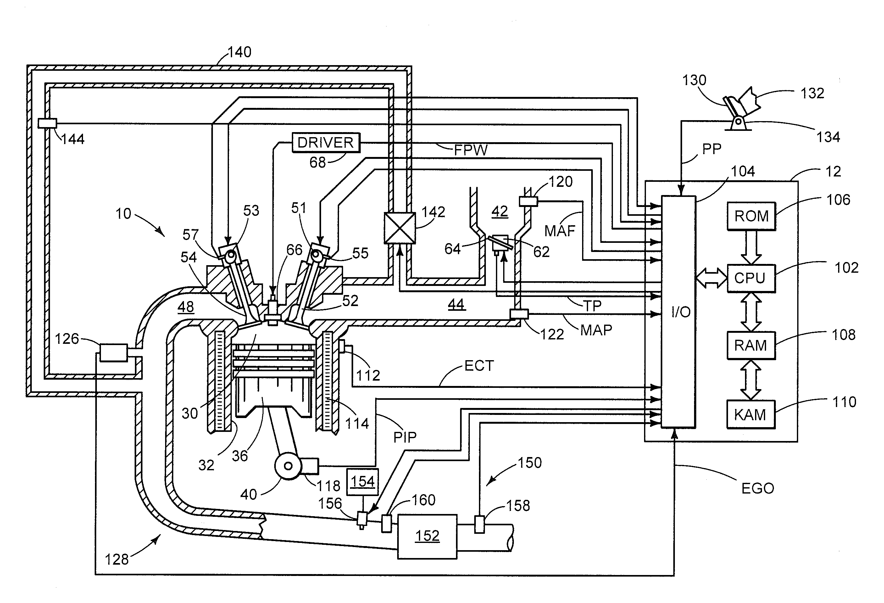
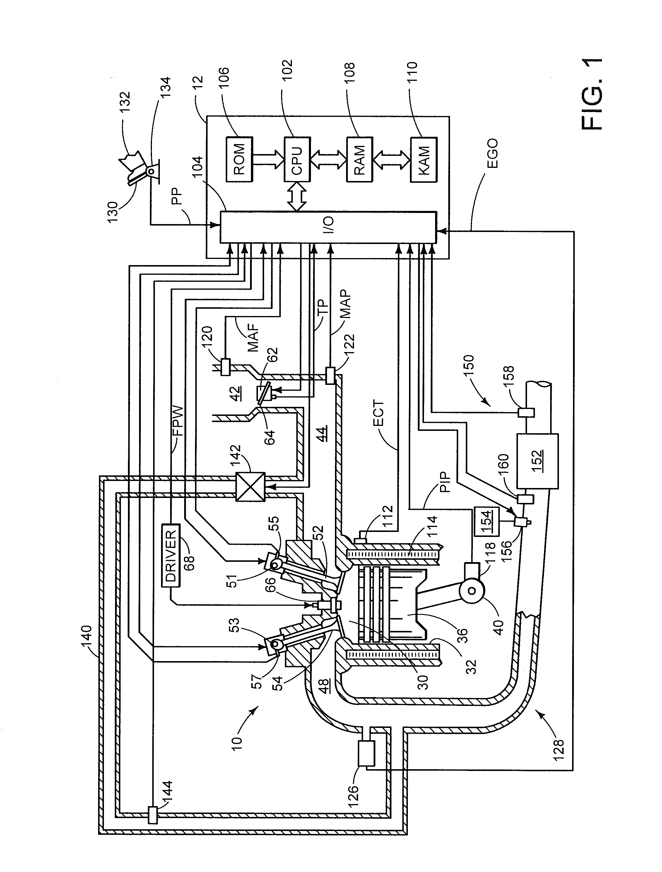
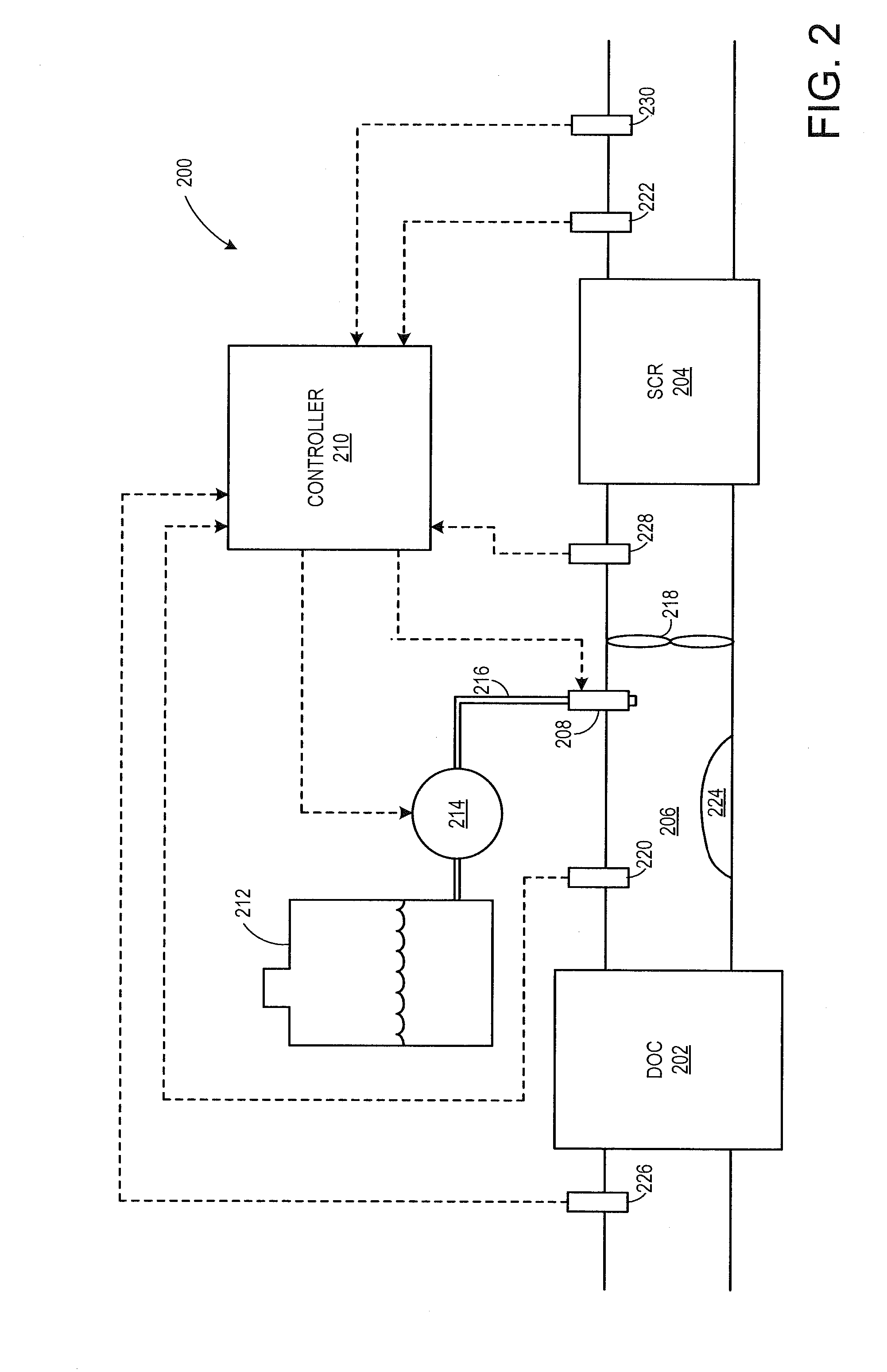
[0016]The following description relates to methods and systems for using an exhaust NOx sensor output generated after an engine shutdown to rest to diagnose exhaust after-treatment system components, such as those included in the engine system of FIG. 1. For example, the method allows for detection of urea deposits in the engine exhaust passage, as shown at FIG. 2. A controller may be configured to perform a control routine, such as the routine of FIG. 3, to identify reductant injector degradation based on the output profile of an exhaust NOx sensor, estimated after the engine has spun to rest, in relation to an expected output profile based on engine conditions. The controller may then adjust reductant dosing control during a subsequent engine start based on an indication of injector leakage, as shown at FIG. 4. The controller may also be configured to perform a control routine, such as the routine of FIG. 5, to inject a known amount of reductant into the exhaust passage after the ...


PUM


Abstract

Various systems and methods for detecting exhaust reductant injector degradation based on an exhaust NOx sensor are disclosed. In one example, degradation of the reductant injector is indicated when an actual NOx sensor output differs from an expected NOx sensor output by more than a threshold amount under engine off conditions.

Description

TECHNICAL FIELD[0001]The present application relates to methods for diagnosing a reductant injector coupled to an exhaust gas treatment system of an internal combustion engine.BACKGROUND AND SUMMARY[0002]Vehicle systems may include an engine with an exhaust gas treatment system coupled in an exhaust passage in order to control regulated emissions. In some examples, the exhaust gas treatment system may include a selective catalytic reduction (SCR) system in which a reductant, such as urea or ammonia, is added to the exhaust stream upstream of a reduction catalyst such that NOx may be reduced by the catalyst. In such an example, the reductant (e.g., urea) may be delivered to the exhaust passage via a reductant injector fluidically coupled to the exhaust passage. Reductant injectors are, however, prone to leakage. In addition, due to poor reductant dosing control, reductant (e.g., ammonia) may be systematically over-injected, leading to formation of deposits in the exhaust passage and ...

Claims


Application Information

Patent Timeline
Patent Type & Authority Applications(United States)
IPC IPC(8): F01N3/18
CPCF01N3/18F01N3/208F01N11/00F01N2550/05F01N2560/026F01N2900/1402F01N3/2066Y02A50/20Y02T10/12Y02T10/40
Inventor UPADHYAY, DEVESHYOO, IN KWANGKUBINSKI, DAVID JOHNVISSER, JACOBUS HENDRIKMEYER, GARTH MICHAELVAN NIEUWSTADT, MICHIEL J.
Owner FORD GLOBAL TECH LLC
Why Eureka
Try Eureka