One-way plate and stator support structure for torque converter using same

a technology of stator support and torque converter, which is applied in the direction of rotary clutches, fluid couplings, gearings, etc., can solve the problems of structure not being able to achieve radial size reduction, and structure cannot implement radial size reduction, so as to reduce the number of components, reduce the radial size of the structure, and reduce the cost

Inactive Publication Date: 2015-05-14
EXEDY CORP
View PDF4 Cites 5 Cited by
  • Summary
  • Abstract
  • Description
  • Claims
  • Application Information

AI Technical Summary

Benefits of technology

[0021]According to the present invention as described above, it is possible to achieve reduction in the number of components and reduction in th...

Problems solved by technology

However, the structure could not have implemented reduction in the number of c...

Method used


Image

  • One-way plate and stator support structure for torque converter using same
  • One-way plate and stator support structure for torque converter using same
  • One-way plate and stator support structure for torque converter using same

Examples


Embodiment Construction

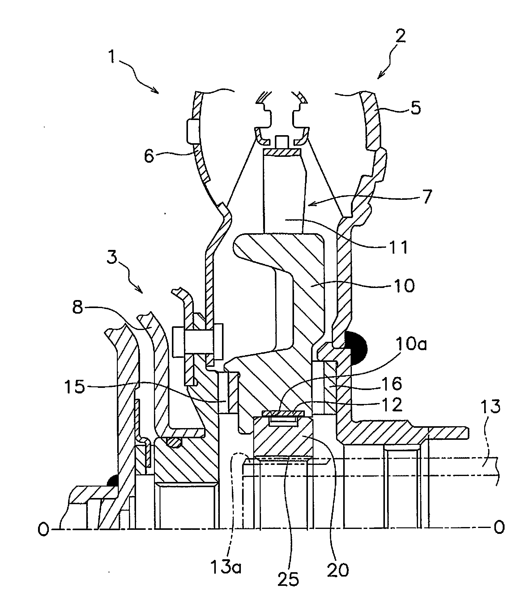
[0026]FIG. 1 partially illustrates a torque converter employing a stator support structure according to an exemplary embodiment of the present invention. A line O-O herein indicates a rotational center line.

[0027]Structure of Torque Converter

[0028]A torque converter 1 includes a torque converter body 2 and a lock-up clutch 3 (only partially illustrated). The torque converter body 2 includes an impeller 5 and a turbine 6 disposed in opposition to each other, and a stator 7. Further, the lock-up clutch 3 includes a piston 8 and so forth.

[0029]The stator 7 is a mechanism disposed between the inner peripheral part of the impeller 5 and that of the turbine 6 to regulate the flow of operating oil returning to the impeller 5 from the turbine 6. The stator 7 is mainly composed of a disc-shaped stator carrier 10 and a plurality of stator blades 11 mounted to the outer peripheral surface of the stator carrier 10. The stator carrier 10 is coupled to a stationary shaft 13 through a one-way plat...


PUM


Abstract

A stator support structure supports a stator of a torque converter on a stationary shaft, and includes an inner race and an annular one-way plate. The inner race is coupled to the stationary shaft to be non-rotatable relative thereto, and has a plurality of protrusions on the outer peripheral surface thereof. The annular one-way plate is mounted to the inner peripheral surface of the stator to be non-rotatable relative thereto, and has a plurality of pawls. The pawls are configured to prevent relative rotation between the stator and the inner race by making contact with first end surfaces formed as one rotation-directional end surfaces of the plural protrusions when the stator is rotated in a first direction. The pawls are configured to allow relative rotation between the stator and the inner race by elastically deforming in a radial direction to climb over the protrusions when the stator is rotated in a second direction.

Description

CROSS-REFERENCE TO RELATED APPLICATIONS[0001]This application is a U.S. National stage application of International Application No. PCT / JP2013 / 071128, filed Aug. 5, 2013, which claims priority to Japanese Patent Application No. 2012-174733, filed in Japan on Aug. 7, 2012, the entire contents of which are hereby incorporated by reference.BACKGROUND[0002]1. Field of Invention[0003]The present invention relates to a one-way plate to be used for restriction in a rotational direction. Further, the present invention relates to a stator support structure for coupling a stator of a torque converter to a stationary shaft with use of the one-way plate.[0004]2. Background Information[0005]A torque converter is a device that includes an impeller, a turbine and a stator in the interior thereof and is configured to transmit power through fluid in the interior thereof. In the torque converter, the stator regulates the direction of the fluid flowing from the turbine to the impeller. As a result, a ...

Claims


Application Information

Patent Timeline
IPC IPC(8): F16D41/12F16H41/24
CPCF16D41/12F16H2041/246F16H41/24
Inventor KAWAMOTO, TAKESHIMOTOTSUNE, KEN
Owner EXEDY CORP
Why Eureka
Try Eureka