
Combined Auger and Screening Apparatus for Screening and Conveyance of Granular Fertilizer or the Like

a screening apparatus and granular fertilizer technology, applied in the field of conveying, can solve the problems of increased cost of repair and/or potential revenue loss, contamination of granular fertilizer, and additional problems

Active Publication Date: 2015-05-14
ANDERSON NEIL
View PDF12 Cites 19 Cited by
  • Summary
  • Abstract
  • Description
  • Claims
  • Application Information

AI Technical Summary

Benefits of technology

The invention is a combined conveyor and screening apparatus that allows for the screening of incoming material. The apparatus includes a housing, a conveyor, an inlet hopper, a screen, a screen support frame, a screen drive mechanism, and a hydraulic circuit. The screen is mounted on the screen support frame, which is carried on the inlet hopper and is driven by the screen drive mechanism. The screen support frame is designed to vibrate the screen in a controlled manner. The apparatus can be easily attached to different conveyors and can be adjusted for different ground surfaces. The invention also includes a kit for outfitting conveyors with screening arrangements. The technical effects of the invention include improved screening efficiency, reduced material waste, and improved operational flexibility.

Problems solved by technology

This is a problem that “EVERY” farmer in the world encounters.
Granular fertilizer has been known to contain contaminants in the form of hardened clumps of fertilizer, stones, wood, bucket elevator bolts and other objects that don't belong in the desired fertilizer product to be applied to agricultural fields.
If these contaminants enter the seeding equipment they can cause plugging, metering roller damage and misapplication of products, and can result in the cost of large repair bills and / or potential revenue loss.
A previously marketed solution is a hydraulic unit called the Lump Buster, by Rainy Day Fabricating Inc., which installs on the end of an auger to “grind” the fertilizer as it passes through, but such a solution does not address the issue of the removal of other contaminants that may be present in the fertilizer, and may also create fertilizer dust, which can attract moisture and cause additional problems.
Other devices for screening granular fertilizer are disclosed in U.S. Pat. Nos. 3,532,276 and 3,610,414, but these are not intended for use in transferring fertilizer from a storage bin to application equipment in a farm setting, and accordingly lack portability and an inclined conveyor operable to elevate material from the bottom outlet of a hopper bin into an air seeder or drill.
Stand alone grain cleaners are also known, but are not suitable for use in screening of granular fertilizer.

Method used


Image

  • Combined Auger and Screening Apparatus for Screening and Conveyance of Granular Fertilizer or the Like
  • Combined Auger and Screening Apparatus for Screening and Conveyance of Granular Fertilizer or the Like
  • Combined Auger and Screening Apparatus for Screening and Conveyance of Granular Fertilizer or the Like

Examples


first embodiment

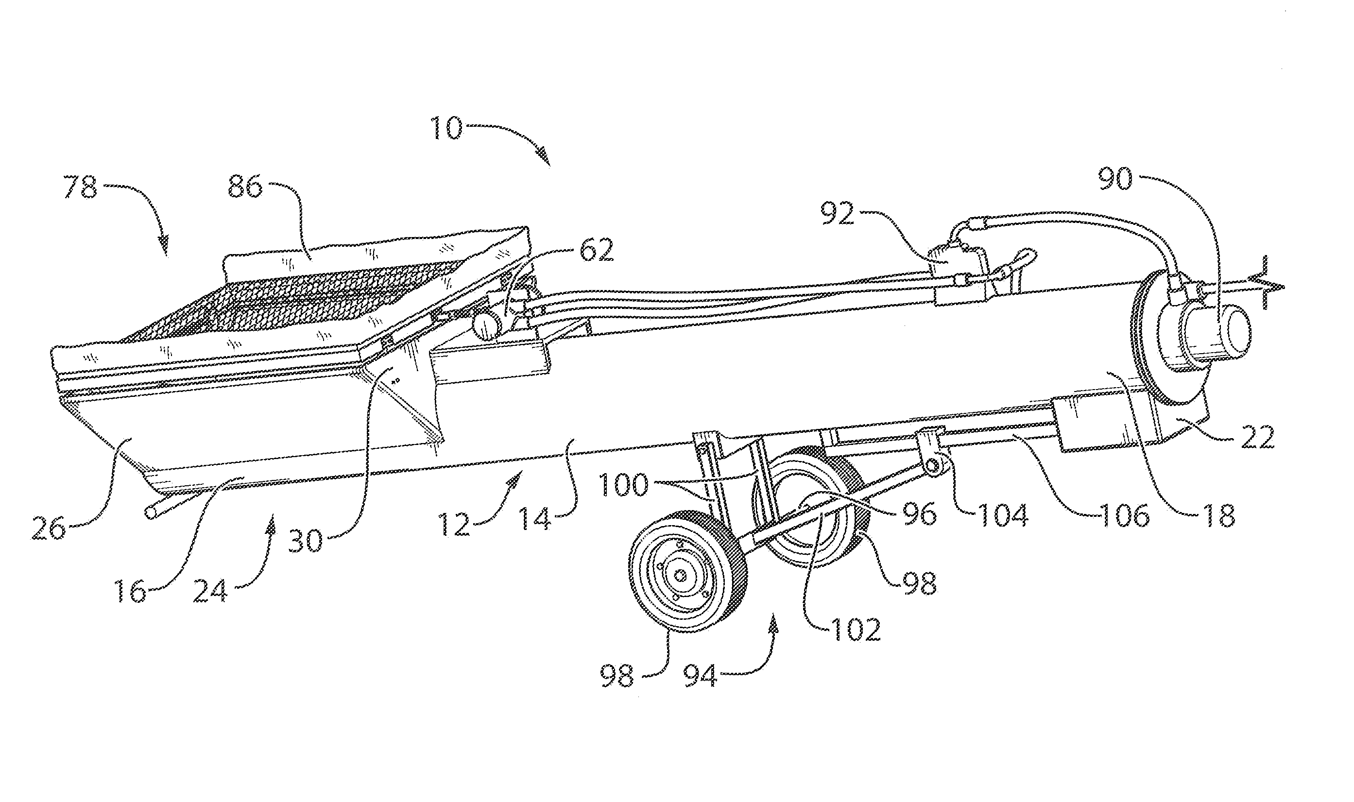
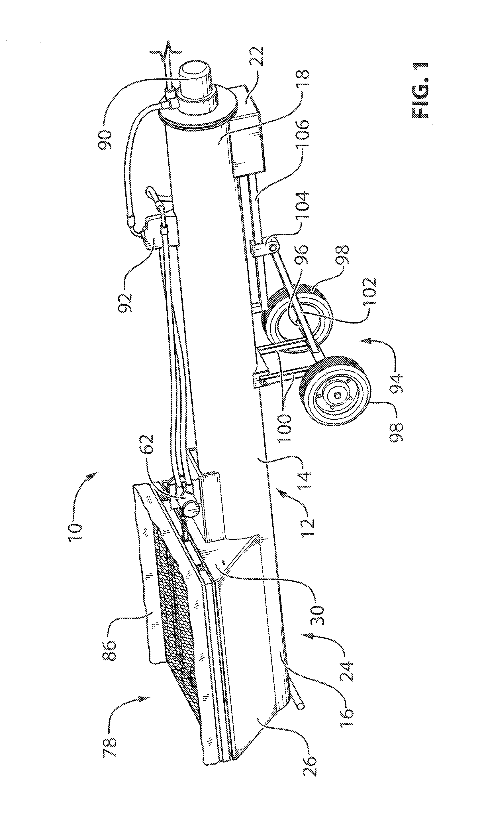
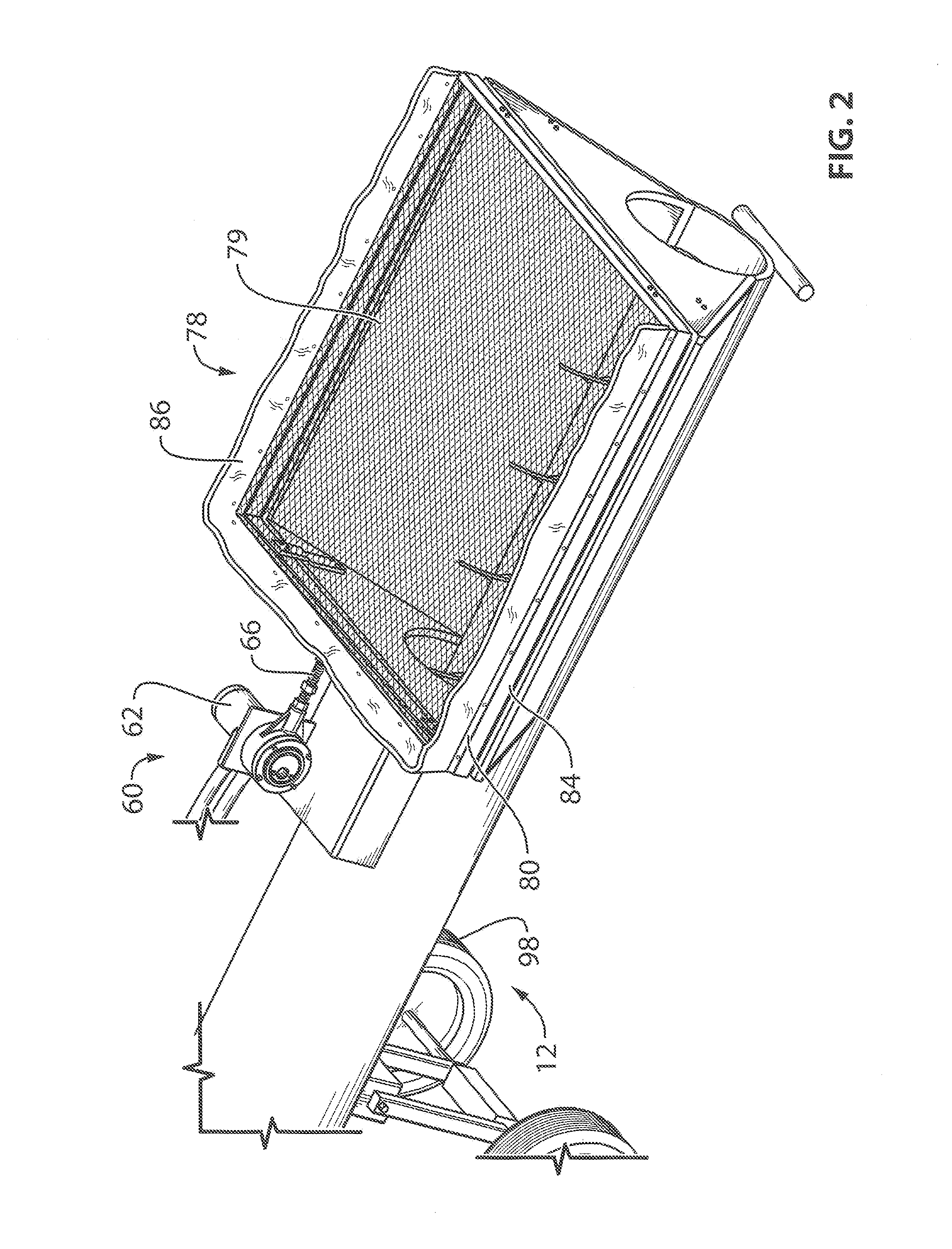
[0058]FIG. 1 shows a combined screening and conveying apparatus for screening and conveying granular fertilizer or other granular or particulate material. The apparatus 10 features an elongated auger housing 12 of conventional shape featuring a tubular cylindrical portion 14 running along a longitudinal axis between an inlet portion 16 at one end of the housing and an outlet portion 18 at an opposing end of the housing. At the inlet portion 16, a topside of the housing features a cutout or opening 20 that defines an inlet by which material is introducible into the interior of the housing from above. At the outlet portion 18, an underside of the housing features a cutout or opening that defines and outlet through which material is discharged from the housing. As shown, a discharge chute or shroud 22 may be provided around the outlet opening to guide the discharged material directly downward from the outlet opening to focus the discharge and minimize lateral spread of the discharged m...

third embodiment

[0097]FIG. 12 shows a third embodiment in which instead of a removable screening unit 78 seated atop a permanently mounted support frame 42, the support frame 42′ is removably supported on the inlet hopper 24, and the screen 79 is permanently affixed to the support frame 42′ to form a screen and support frame assembly 300. The skirting is omitted for ease of illustration, but is preferably included in such embodiments. At one of the hopper end walls 30, at or near the open top end of the hopper, a first pair of support blocks or bushings 302 are affixed to the inside surface of the end wall 30, and each feature an cylindrical opening 302a extending into the block from an thereof lying opposite the end wall 30 in an axial direction toward the end wall 30.

[0098]At the other end wall 32 of the hopper, a second pair of support blocks or bushings 304 (shown in broken lines) are affixed to the inside surface of the end wall 30, and each feature an cylindrical opening extending into the bl...

second embodiment

[0101]The slider blocks 308 may be made of low friction material, coated with a low friction coating or lubricant at the cylindrical through-bores 308a thereof that receive the guide shafts 306, or incorporate bearings or bushings at this sliding interface. Also, the term block is not intended to denote a specific shape or structure of these sliding blocks 308, which accordingly may also be referred to more generally as slide members. The slide members and guide shafts effectively form a linear bearing mechanism by which the removable support frame and screen assembly is supported for oscillation by the drive mechanism. The assembly is easily installed and removed without the use of tools by inserting and laying the guide shafts in the support blocks for installation, and withdrawing and lifting the guide shafts out of the support blocks for removal. The only permanent installation is the mounting blocks. Together with the removable drive mechanism of the second embodiment, the supp...


PUM

PropertyMeasurementUnit
Angleaaaaaaaaaa
Poweraaaaaaaaaa
Speedaaaaaaaaaa

Abstract

A combined auger conveyor and screening apparatus features an inlet hopper mounted to an auger housing adjacent an inlet end thereof, and a screen support frame disposed atop the inlet hopper and supporting a screen over an area of the inlet hopper. A screen drive mechanism is removably mounted to the auger housing, coupled to the screen support frame and operable to drive oscillatory motion of the screen. An angle adjustment mechanism is operable to vary a position of ground wheels relative to the auger housing in order to change an inclination angle of the auger housing and screen relative to the ground. A hydraulic circuit supplying hydraulic motors for both the auger and the screen drive mechanism comprises a control valve operable to adjust an oscillatory speed of the screen support frame.

Description

CROSS REFERENCE TO RELATED APPLICATIONS[0001]This application claims benefit under 35 U.S.C. 119(e) of Provisional Application Ser. No. 61 / 904,144, filed Nov. 14, 2013.FIELD OF THE INVENTION[0002]The present invention relates generally to conveyors, and more particularly to an auger unit featuring a built in screening mechanism for screening of material before it enters the auger, for example for use in unloading granular fertilizer from a storage bin in an agricultural setting.BACKGROUND OF THE INVENTION[0003]The present application discloses a transfer auger that screens / scalps foreign material out of granular fertilizer as it transfers from the storage bin to the seeding / fertilizing equipment subsequently used to apply the fertilizer in the field. This is a problem that “EVERY” farmer in the world encounters.[0004]Granular fertilizer has been known to contain contaminants in the form of hardened clumps of fertilizer, stones, wood, bucket elevator bolts and other objects that don'...

Claims


Application Information

Patent Timeline
IPC IPC(8): B07B1/28B07B1/46
CPCB07B1/46B07B1/28B07B1/30B07B1/42Y10T29/49716B07B1/005
Inventor ANDERSON, NEIL
Owner ANDERSON NEIL
Learn More