Method and apparatus for power-up detection for an electrical monitoring circuit

Active Publication Date: 2015-05-14
ADVANCED MICRO DEVICES INC
View PDF3 Cites 9 Cited by
  • Summary
  • Abstract
  • Description
  • Claims
  • Application Information

AI Technical Summary

Benefits of technology

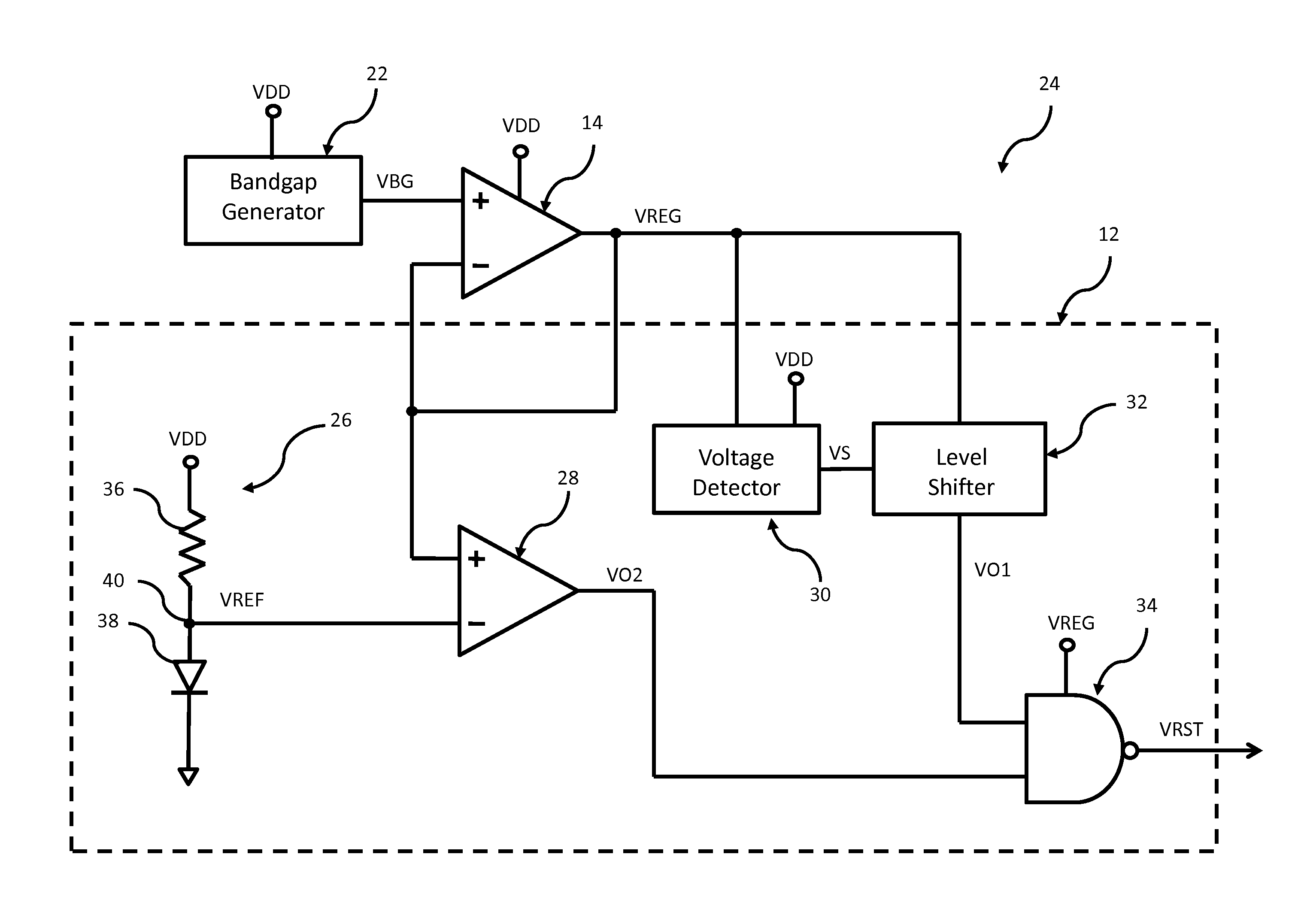
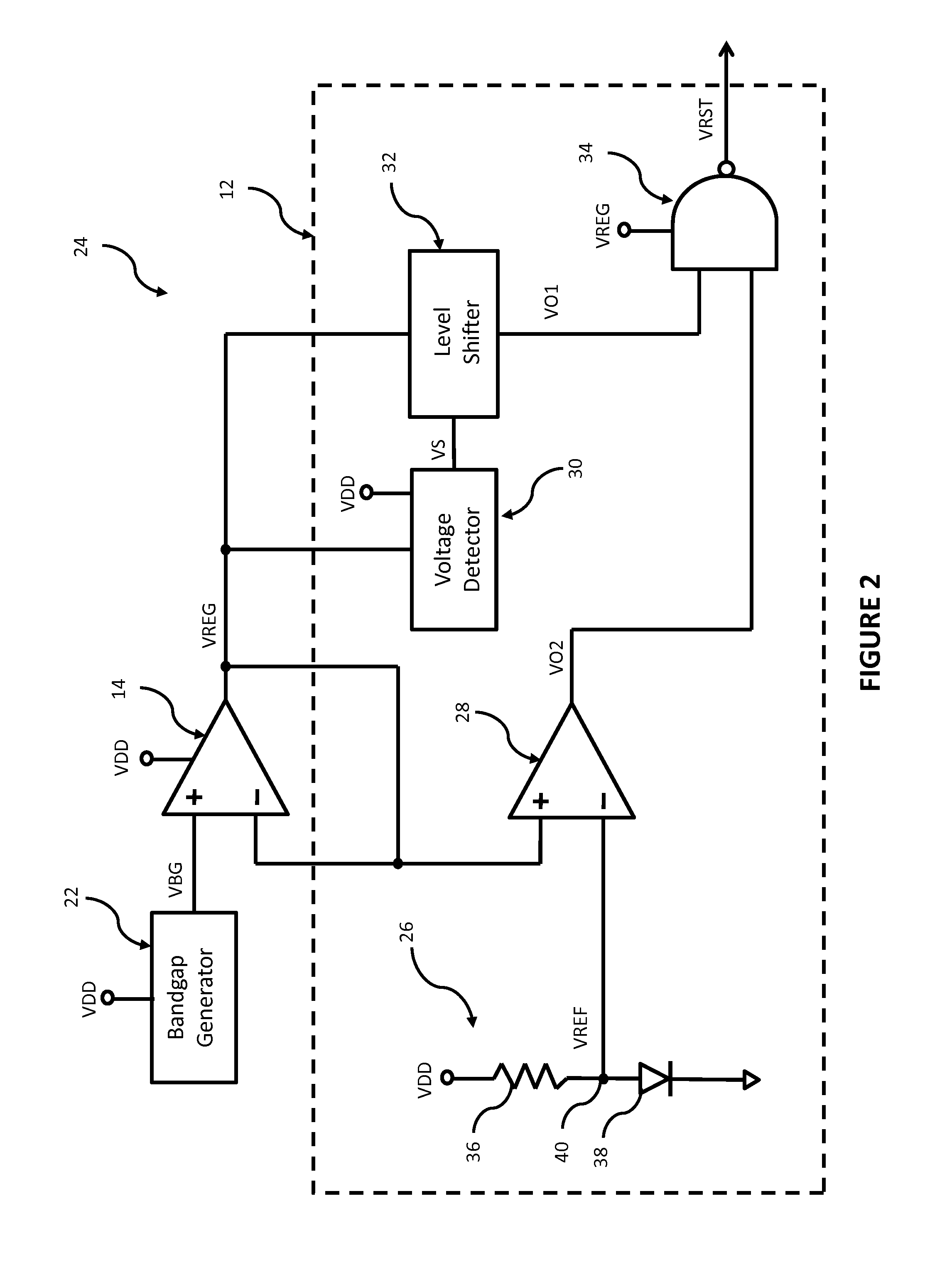
[0007]According to one embodiment of the present disclosure, an apparatus for outputting a reset signal during power-up until two conditions are satisfied, comprises a voltage detector that provides a first output (“VO1”) when an output voltage of a regulator (“VREG”) exceeds a threshold voltage, thereby satisfying a first condition, a comparator receiving a first input voltage and a second input voltage, the comparator providing a second output (“VO2”) when the first input voltage exceeds the second input voltage, thereby satisfying a second condition, and a release circuit that outputs the reset signal unless the voltage detector provides VO1 while the comparator provides VO2. One aspect of this embodiment further comprises a reference circuit that provides a reference voltage (“VREF”) as the second input voltage to the comparator, VREF corresponding to a voltage drop of a supply voltage across a diode. In a variant of this aspect, VREG is the first input voltage to the comparator. Another aspect of this embodiment further comprises a reference circuit that provides a first voltage (“VDIV”) as the first input voltage to the comparator and a second voltage (“VREF”) as the second input voltage to the comparator, VDIV corresponding to an output voltage of a voltage divider having a supply voltage as an input and VREF corresponding to a voltage drop of the supply voltage across a diode. Yet another aspect of this embodiment further comprises a reference circuit that provides a first voltage (“VDIV1”) as the first input voltage to the comparator and a second voltage (“VDIV2”) as the second input voltage to the comparator, VDIV1 corresponding to an output voltage of a first voltage divider having a supply voltage as an input and VDIV2 corresponding to an output voltage of a second voltage divider having VREG as an input. In still another aspect, the regulator provides VREG as a function of a bandgap generator output (“VBG”). In another aspect, the release circuit is a NAND gate having VO1 as one input and VO2 as another input. In yet another aspect, the voltage detector includes a transistor having a gate connected to VREG and a source connected through an input resistor to a supply voltage, a voltage at the gate of the transistor being the threshold voltage.
[0008]According to another embodiment of the present disclosure, a method of determining whether to output a reset signal during power-up to prevent operation of a digital monitoring circuit until two conditions are satisfied, comprises generating a first output (“VO1”) when an output voltage of a regulator (“VREG”) exceeds a threshold voltage, thereby satisfying a first condition, comparing a first input voltage and a second input voltage, generating a second output (“VO2”) when the first input voltage exceeds the second input voltage, thereby satisfying a second condition, outputting the reset signal in the absence of one or both of VO1 and VO2, and not outputting the reset signal when both VO1 and VO2 are generated. One aspect of this embodiment further comprises providing a reference voltage (“VREF”) as the second input voltage, VREF corresponding to a voltage drop of a supply voltage across a diode. In a variant of this asp

Problems solved by technology

Unfortunately, hackers sometimes purchase consoles with the goal of identifying the encryption keys used to protect the contents of the chip.
One method hackers use to gain access to the encryption keys is to change the operating parameters of the chip to place it in an undesirable mode of operation.
When in such an undesirable mode, the chip's standard security circuits may be non-functional, thereby permitting access to the encryption keys, and then the proprietary content.
For example, if a chip is forced to operate under very high or very low ambient temperatures, the chip may operate in an undesirable mode.
Similarly, if any of a variety of voltage inputs to the chip are increased or decreased beyond certain limits, the chip may operate in an und

Method used


Image

  • Method and apparatus for power-up detection for an electrical monitoring circuit
  • Method and apparatus for power-up detection for an electrical monitoring circuit
  • Method and apparatus for power-up detection for an electrical monitoring circuit

Examples


Example

[0023]Briefly, in one example, a method and apparatus for outputting a reset signal during power-up until two conditions are satisfied includes a voltage detector that provides a first output (“VO1”) when an output voltage of a regulator (“VREG”) exceeds a threshold voltage, thereby satisfying a first condition, a comparator receiving a first input voltage and a second input voltage, the comparator providing a second output (“VO2”) when the first input voltage exceeds the second input voltage, thereby satisfying a second condition, and a release circuit that outputs the reset signal unless the voltage detector provides VO1 while the comparator provides VO2. In certain embodiments, the first and second input voltages to the comparator correspond to characteristics of a supply voltage and / or characteristics of VREG. Thus, the present disclosure provides a method and apparatus which maintains a reset signal during power-up (which prevents operation of the circuit receiving the reset si...


PUM


Abstract

A method and apparatus is provided for outputting a reset signal during power-up until two conditions are satisfied. In one embodiment, the method and apparatus includes a voltage detector that provides a first output (“VO1”) when an output voltage of a regulator (“VREG”) exceeds a threshold voltage, thereby satisfying a first condition, a comparator receiving a first input voltage and a second input voltage, the comparator providing a second output (“VO2”) when the first input voltage exceeds the second input voltage, thereby satisfying a second condition, and a release circuit that outputs the reset signal unless the voltage detector provides VO1 while the comparator provides VO2.

Description

CROSS-REFERENCE TO RELATED APPLICATIONS[0001]This application claims priority to and the benefit of U.S. Provisional Application Ser. No. 61 / 904,307, filed Nov. 14, 2013.BACKGROUND OF THE DISCLOSURE[0002]The disclosure relates generally to a method and apparatus for power-up detection for an electrical monitoring circuit which, in one application, may be used to prevent unauthorized access to chip contents.[0003]Many complex processors such as those including systems on a chip (“SoC”) and used in video game consoles, store digital media content that is copyrighted or other proprietary information that needs to be secure. Such data is typically stored and transmitted in an encrypted format. Unfortunately, hackers sometimes purchase consoles with the goal of identifying the encryption keys used to protect the contents of the chip. With the encryption keys identified, the hacker can decrypt the content and exploit it in a variety of ways.[0004]One method hackers use to gain access to t...

Claims


Application Information

Patent Timeline
IPC IPC(8): H03K3/01
CPCH03K3/01H03K17/22
Inventor AMICK, BRIAN W.TALBOT, GERALD R.ANDERSON, WARREN
Owner ADVANCED MICRO DEVICES INC
Why Eureka
Try Eureka