Antenna device and wireless apparatus including same

a wireless apparatus and antenna technology, applied in the direction of resonant antennas, elongated active element feeds, independent non-interfering antenna combinations, etc., can solve the problems of antenna inoperableness, large variation of capacitance value, and damage to housings

Active Publication Date: 2015-05-14
ASAHI GLASS CO LTD
View PDF2 Cites 17 Cited by
  • Summary
  • Abstract
  • Description
  • Claims
  • Application Information

AI Technical Summary

Problems solved by technology

In a case where a brittle material such as glass or ceramics is used for a housing on which antennas are formed and a feed pin is used for feeding, the housing may be damaged and the antennas may become inoperable when a strong external impact is applied to the housing and stress is concentrated on one point on the housing.
However, with a feeding mechanism where a radiating conductor and a capacitor plate are capacitively coupled, its capacitance value greatly varies when the positional relationship between the radiating conductor and the capacitor plate, particularly a gap between them, becomes different from a designed value due to, for example, a production error.
This in turn makes it difficult to achieve impedance matching.
Also, the same problem may occur when the positional relationship between the radiating conductor and the capacitor plate changes due to vibration during use.

Method used


Image

  • Antenna device and wireless apparatus including same
  • Antenna device and wireless apparatus including same
  • Antenna device and wireless apparatus including same

Examples


Embodiment Construction

[0048]Embodiments of the present invention are described below with reference to the accompanying drawings.

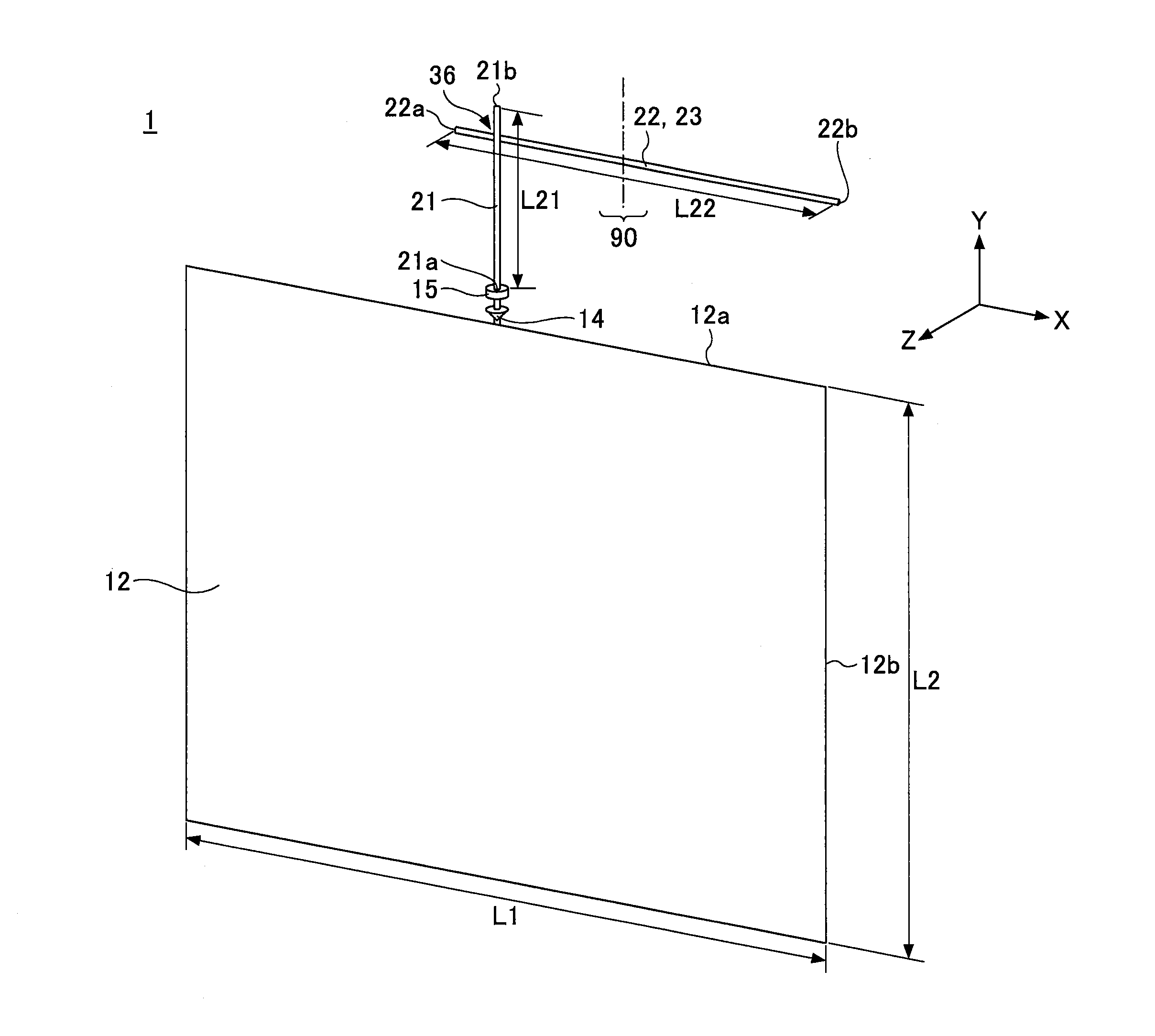
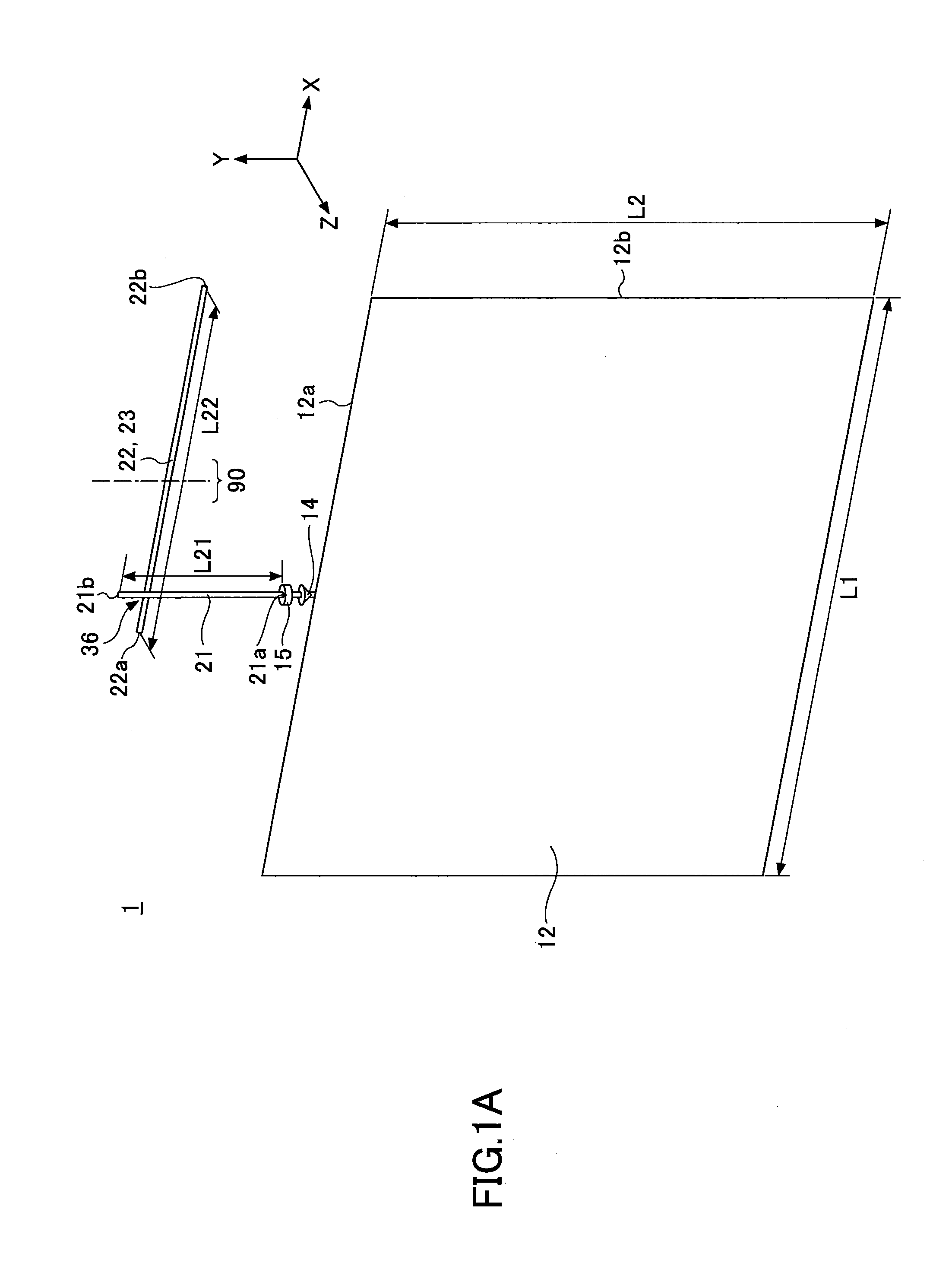
[0049]FIG. 1A is a perspective view of a computer simulation model for analyzing operations of an antenna device 1 according to an embodiment of the present invention. Microwave Studio (registered trademark) (CST Computer Simulation Technology AG) is used as an electromagnetic field simulator.

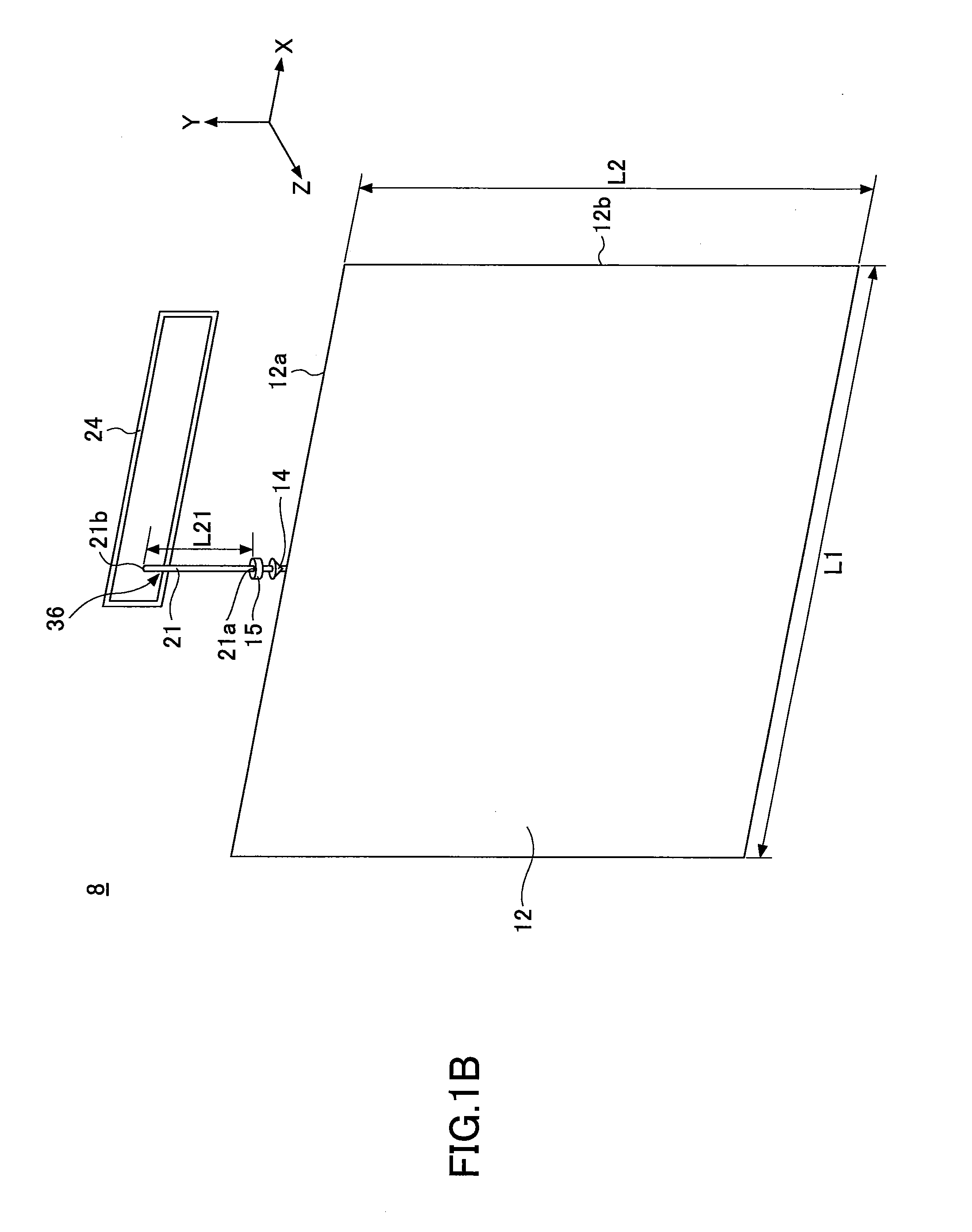
[0050]The antenna device 1 includes a feed point 14, a ground plane 12, a radiating element 22, a feeding part 36 for feeding the radiating element 22, and a feeding element 21 that is a conductor and disposed at a predetermined distance from the radiating element 22 in a Z-axis direction. The feeding part 36 is a feeding part solely for the radiating element 22, and is not for the antenna device 1. A feeding part for the antenna device 1 is the feed point 14.

[0051]In the example of FIG. 1A, the radiating element 22 and the feeding element 21 overlap each other in plan view seen from the Z...


PUM


Abstract

An antenna device includes a feeding element connected to a feed point, and a radiating element disposed at a distance from the feeding element. The feeding element is coupled with the radiating element by electromagnetic field coupling to feed the radiating element so that the radiating element functions as a radiating conductor.

Description

CROSS-REFERENCE TO RELATED APPLICATIONS[0001]The present application is a continuation application filed under 35 U.S.C. 111(a) claiming benefit under 35 U.S.C. 120 and 365(c) of PCT International Application No. PCT / JP2013 / 067135, filed on Jun. 21, 2013, which is based on and claims the benefit of priority of Japanese Patent Application No. 2012-161983 filed on Jul. 20, 2012, the entire contents of which are incorporated herein by reference.BACKGROUND OF THE INVENTION[0002]1. Field of the Invention[0003]An aspect of this disclosure relates to an antenna device and a wireless apparatus including the antenna device.[0004]2. Description of the Related Art[0005]In recent years, the number of antennas provided in, for example, a portable wireless apparatus has increased and the integration density of a circuit board of such a portable wireless apparatus has increased. For this reason, antennas are disposed, for example, on or in a housing of a portable wireless apparatus away from a cir...

Claims


Application Information

Patent Timeline
Patent Type & Authority Applications(United States)
IPC IPC(8): H01Q1/50H01Q5/10
CPCH01Q1/50H01Q7/00H01Q9/065H01Q21/28H01Q9/42H01Q1/243H01Q5/364H01Q5/378
Inventor SONODA, RYUTAIKAWA, KOJISAYAMA, TOSHIKI
Owner ASAHI GLASS CO LTD
Why Eureka
Try Eureka