Laminated balance filter

a technology of balance filter and filter body, which is applied in the direction of waveguide, waveguide type device, electrical apparatus, etc., can solve the problems of difficult to selectively design the impedance, and difficult to reduce the size of the filter, so as to achieve the effect of reducing the siz

Active Publication Date: 2011-06-16
MURATA MFG CO LTD
View PDF4 Cites 14 Cited by
  • Summary
  • Abstract
  • Description
  • Claims
  • Application Information

AI Technical Summary

Benefits of technology

[0009]To overcome the problems described above, preferred embodiments of the present invention provide a laminated balance filter that is easily reduced in size and that can perform predetermined impedance conversion between an input and an output.

Problems solved by technology

However, since balance characteristics are obtained using stripline coupling in the structure illustrated in Japanese Unexamined Patent Application Publication No. 2005-45447, it is difficult to selectively design the impedance.
Since a ½ wave length stripline is used to balance the characteristics, it is difficult to reduce the size thereof.
In addition, if an impedance converting circuit is provided, an area occupied by the impedance converting circuit increases, and thus, it is difficult to reduce the size of the filter.

Method used


Image

  • Laminated balance filter
  • Laminated balance filter
  • Laminated balance filter

Examples


first preferred embodiment

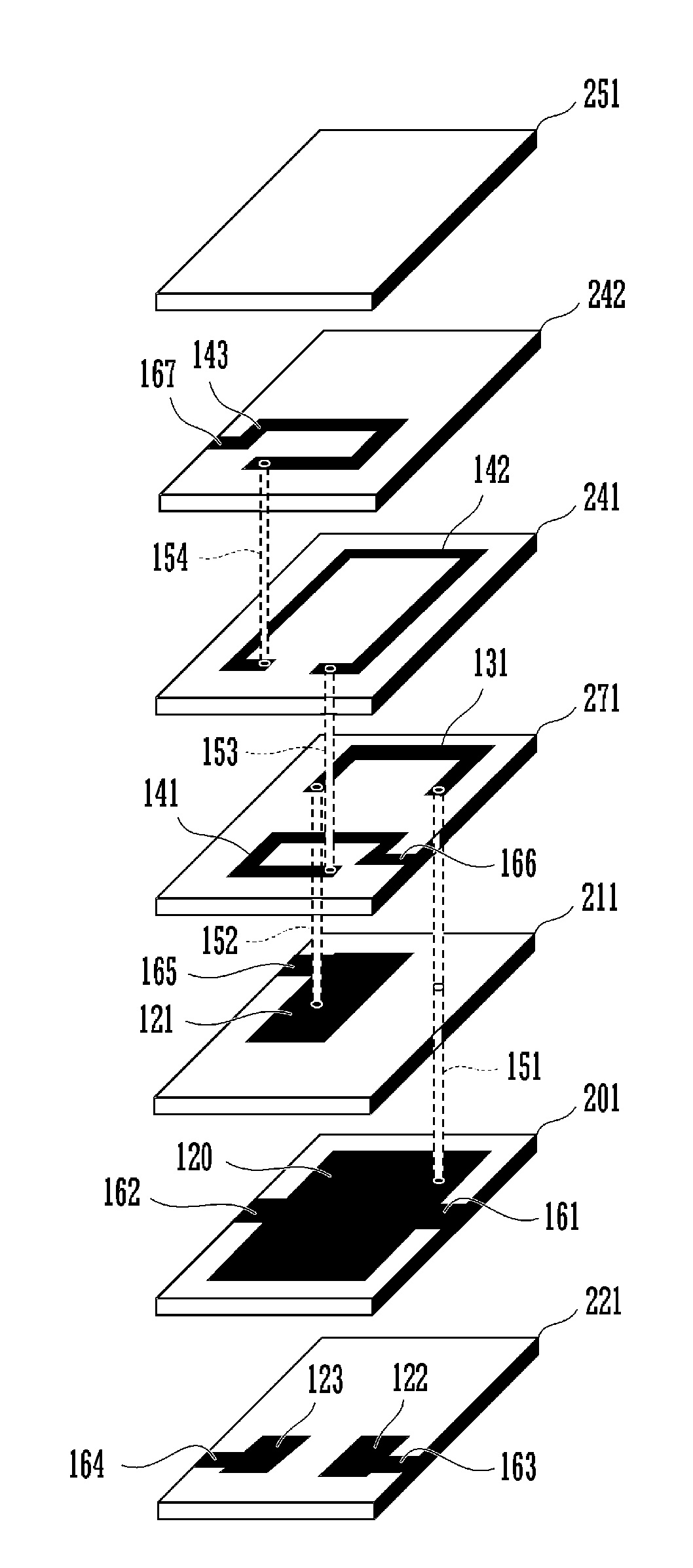
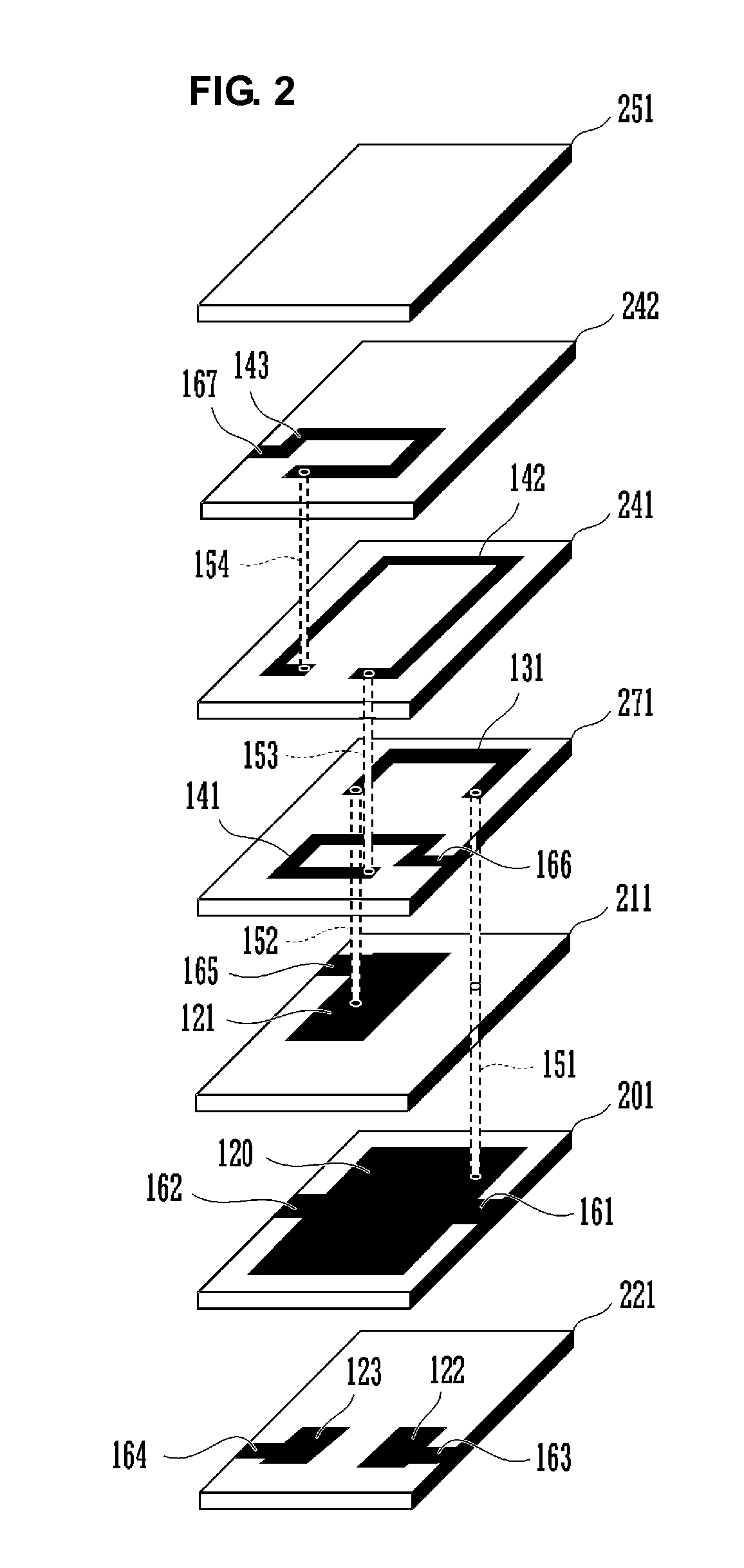
[0048]A laminated balance filter according to a first preferred embodiment of the present invention will be described with reference to FIGS. 2 to 4. FIG. 2 is an exploded perspective view of the laminated balance filter according to the first preferred embodiment of the present invention.

[0049]As illustrated in FIG. 2, the laminated balance filter includes a multilayer body including a plurality of laminated dielectric layers 251, 242, 241, 271, 211, 201, and 221 on which electrode patterns are provided. When the multilayer body is formed by firing, a plurality of dielectric green sheets in which electrode patterns are individually provided are laminated, pressed, and fired. Therefore, while the dielectrics after firing are combined, the dielectrics do not necessarily define individual layers. However, since a dielectric having a predetermined thickness is disposed between adjacent electrode layers, it may be assumed that a dielectric layer and an electrode layer are laminated in t...

second preferred embodiment

[0074]FIG. 5 is an exploded perspective view of a laminated balance filter according to a second preferred embodiment of the present invention.

[0075]As illustrated in FIG. 5, the laminated balance filter includes a multilayer body including a plurality of laminated dielectric layers 251, 242, 241, 271, 242, 211, 201, and 221 in which electrode patterns are provided.

[0076]The laminated balance filter is different from the laminated balance filter according to the first preferred embodiment illustrated in FIG. 2 in that the center of the center coil 142 located in the center of the three balanced side coils extends to the left side of the dielectric layer 242 through extraction electrodes 171 and 172 and a via electrode 155.

[0077]The remaining configuration is the same or substantially the same as that of the first preferred embodiment.

[0078]FIG. 6 is a perspective view of a laminated balance filter 12 according to the second preferred embodiment.

[0079]By laminating the dielectric lay...

third preferred embodiment

[0082]FIG. 8 is an exploded perspective view of a laminated balance filter according to a third preferred embodiment of the present invention.

[0083]As illustrated in FIG. 8, the laminated balance filter includes a multilayer body including a plurality of laminated dielectric layers 251, 231, 243, 253, 244, 242, 241, 252, 211, 201, and 221 in which electrode patterns are provided.

[0084]In the dielectric layer 211, a first capacitor electrode 121 is provided. The capacitor electrode 121 extends to the left side of the dielectric layer 211 through an extraction electrode 165. A ground electrode 120 is provided in the dielectric layer 201. The ground electrode 120 extends to the right and left sides of the dielectric layer 201 through extraction electrodes 161 and 162. A second capacitor electrode 122 and a third capacitor electrode 123 are provided in the dielectric layer 221. The second capacitor electrode 122 extends to the right side of the dielectric layer 221 through an extraction...


PUM


Abstract

A laminated balance filter includes a first capacitor electrode and a ground electrode that are disposed opposite to each other to define a capacitor at an unbalanced side. An unbalanced side coil is provided in a dielectric layer. Three balanced side coils are provided in three dielectric layers. The three balanced side coils preferably have a substantially helical shape and are wound in the same winding directions. The coil located in the center of the three balanced side coils is disposed near the unbalanced side coil so as to be electromagnetic-field-coupled to the unbalanced side coil.

Description

BACKGROUND OF THE INVENTION[0001]1. Field of the Invention[0002]The present invention relates to a laminated balance filter having a multilayer body including a plurality of dielectric layers and a plurality of electrode layers.[0003]2. Description of the Related Art[0004]In recent years, high-frequency band pass filters having a reduced size and cost include a plurality of LC resonators in a multilayer body in which a dielectric layer and an electrode layer are laminated. An example of such a multilayer band pass filter is disclosed in Japanese Unexamined Patent Application Publication No. 2005-45447. The configuration of a multilayer band pass filter disclosed in Japanese Unexamined Patent Application Publication No. 2005-45447 will be described with reference to FIG. 1.[0005]FIG. 1 is a circuit diagram of the multilayer band pass filter disclosed in Japanese Unexamined Patent Application Publication No. 2005-45447. A multilayer band pass filter 1 includes an unbalanced input 2, b...

Claims


Application Information

Patent Timeline
Patent Type & Authority Applications(United States)
IPC IPC(8): H03H7/01
CPCH03H7/09H03H7/1775H03H7/42H03H2001/0085
Inventor TANIGUCHI, TETSUO
Owner MURATA MFG CO LTD
Why Eureka
Try Eureka