Duplexer and lamination type high frequency device using said duplexer and communication equipment

A technology of duplexers and laminates, applied in waveguide devices, electrical components, circuits, etc., can solve problems such as complex circuit configuration, larger configuration space, and increased loss of splitter circuits

Inactive Publication Date: 2004-05-19
PANASONIC CORP
View PDF0 Cites 14 Cited by
  • Summary
  • Abstract
  • Description
  • Claims
  • Application Information

AI Technical Summary

Problems solved by technology

[0017] However, the circuit configuration of the above-mentioned structure is complicated, so there are problems that the loss of the wave splitting circuit is increased and the arrangement space is inevita

Method used


Image

  • Duplexer and lamination type high frequency device using said duplexer and communication equipment
  • Duplexer and lamination type high frequency device using said duplexer and communication equipment
  • Duplexer and lamination type high frequency device using said duplexer and communication equipment

Examples


no. 1 Embodiment approach

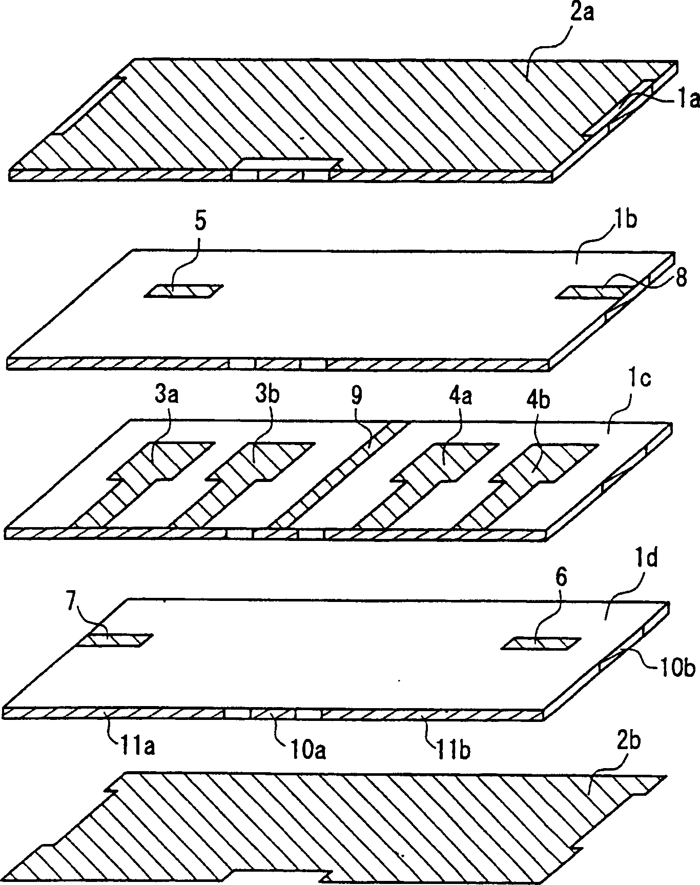
[0178] figure 2 It is an exploded perspective view showing the duplexer according to the first embodiment of the present invention.

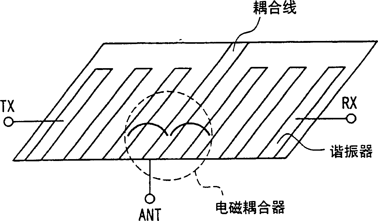
[0179] Such as figure 2 As shown, the duplexer of this embodiment is composed of a laminate in which dielectric layers and electrode layers are alternately stacked. A first filter for transmission and a second filter for reception having different transmission band frequencies are provided in the laminated body. Between the first filter and the second filter, a matching circuit composed of a coupling line 9 with one end short-circuited and the other end connected to an external terminal is provided.

[0180] The first filter includes two first stripline resonators 3a, 3b with one end short-circuited. The second filter includes two second stripline resonators 4a, 4b with one end short-circuited. The coupled line 9 and the first strip line resonator 3b adjacent to the coupled line are coupled by electromagnetic field coupling. The coupled l...

no. 2 Embodiment approach

[0193] Image 6 It is an exploded perspective view showing a duplexer according to a second embodiment of the present invention. The duplexer of this embodiment is the same as the duplexer of the first embodiment except for the following points, so the same or corresponding parts are given the same reference numerals and their descriptions are omitted.

[0194] Such as Image 6 As shown, in the duplexer of this embodiment, the first stripline resonators 3a, 3b and the second stripline resonators 4a, 4b are respectively formed on a dielectric layer 1c different from the dielectric layer 1d on which the coupling line 9 is formed. , 1e. In this way, by forming the first stripline resonators 3a, 3b and the second stripline resonators 4a, 4b on the dielectric layers 1c, 1e different from the dielectric layer 1d on which the coupling line 9 is formed, the duplex The appliance has design freedom and versatility.

[0195] The coupling line 9 is composed of two dielectric strip lin...

no. 3 Embodiment approach

[0199] Figure 7 It is an exploded perspective view showing a duplexer according to a third embodiment of the present invention. The duplexer of this embodiment is the same as the duplexer of the above-mentioned second embodiment except for the following points, so the same or corresponding parts are given the same reference numerals and their descriptions are omitted.

[0200] Such as Figure 7 As shown, in the duplexer of this embodiment, the coupling line is composed of three dielectric striplines 9a, 9b, 9c, and the three dielectric striplines 9a, 9b, 9c are respectively arranged on different dielectric layers 1c, 1d, 1e . When there is only one dielectric stripline, the potential fluctuates, but by using three dielectric striplines, the potential can be stabilized.

[0201] Preferably at least one of the three dielectric striplines 9a, 9b, 9c has a different line width than the other dielectric striplines. The dielectric strip lines 9a, 9b, and 9c of this embodiment h...


PUM


Abstract

To obtain a duplexer which can be realized in an extremely simple structure and is capable of remarkably reducing a loss. The duplexer is composed of a laminate wherein dielectric layers and electrode layers are alternately laminated. Within the laminate, a first filter for transmission and a second filter for reception of mutually different passband frequencies are provided. A matching circuit composed of a coupling line (9) of which one terminal is short-circuited and of which the other terminal is connected to an external terminal is provided between the first filter and the second filter. The first filter includes two first strip line resonators (3a, 3b) of which one terminal is short-circuited. The second filter includes two second strip line resonators (4a, 4b) of which one terminal is short-circuited. The coupling line (9) and the first strip line resonator (3b) proximate to the coupling line (9) are coupled by electromagnetic field coupling. The coupling line (9) and the second strip line resonator (4a) proximate to the coupling line (9) are coupled by electromagnetic field coupling.

Description

technical field [0001] The present invention relates to a duplexer (duplexer) and a laminated high-frequency device and communication equipment using the duplexer. Specifically, it relates to a common antenna for the sender and the receiver, and has the function of transmitting the signal and the receiver. An antenna duplexer with a function of separating reception signals, and a stacked high-frequency device and communication equipment using the antenna duplexer. Background technique [0002] The sender and receiver share a single antenna, and the antenna duplexer, which has the function of separating the send signal and the receive signal, is connected to two filters with different center frequencies. Therefore, the center frequency of any one of the two filters should be such that the impedance of the other filter is infinite when viewed from the common input and output terminals of the two filters, that is, the antenna, and does not interfere with the frequency of the fi...

Claims


Application Information

Patent Timeline
IPC IPC(8): H01P1/203H01P1/205H01P1/212H01P1/213
Inventor 前川智哉繁村广志
Owner PANASONIC CORP
Why Eureka
Try Eureka