Optical logic gates and method for generating logic signals using DNA based nanostructure

a technology of optical logic gates and nanostructures, applied in nanoinformatics, instruments, pulse techniques, etc., can solve the problems of difficult characteristic control according to wavelength, light with great intensity, and the physical limit of conventional semiconductor based information processing techniques

Active Publication Date: 2015-05-14
KOREA INST OF SCI & TECH
View PDF3 Cites 2 Cited by
  • Summary
  • Abstract
  • Description
  • Claims
  • Application Information

AI Technical Summary

Problems solved by technology

However, the conventional semiconductor based information processing technique has recently reached the physical limit in its processing rate and degree of integration.
However, in order to implement a non-linear characteristic of general optical elements, light with great intensity is required, which becomes an obstacle in applying the non-linear optical technique to a logic circuit.
However, this wave plate has problems of difficult characteristic control according to wavelengths, difficult in miniaturization and integration, and high production costs.

Method used


Image

  • Optical logic gates and method for generating logic signals using DNA based nanostructure
  • Optical logic gates and method for generating logic signals using DNA based nanostructure
  • Optical logic gates and method for generating logic signals using DNA based nanostructure

Examples


Embodiment Construction

[0022]Exemplary embodiments now will be described more fully hereinafter with reference to the accompanying drawings, in which exemplary embodiments are shown

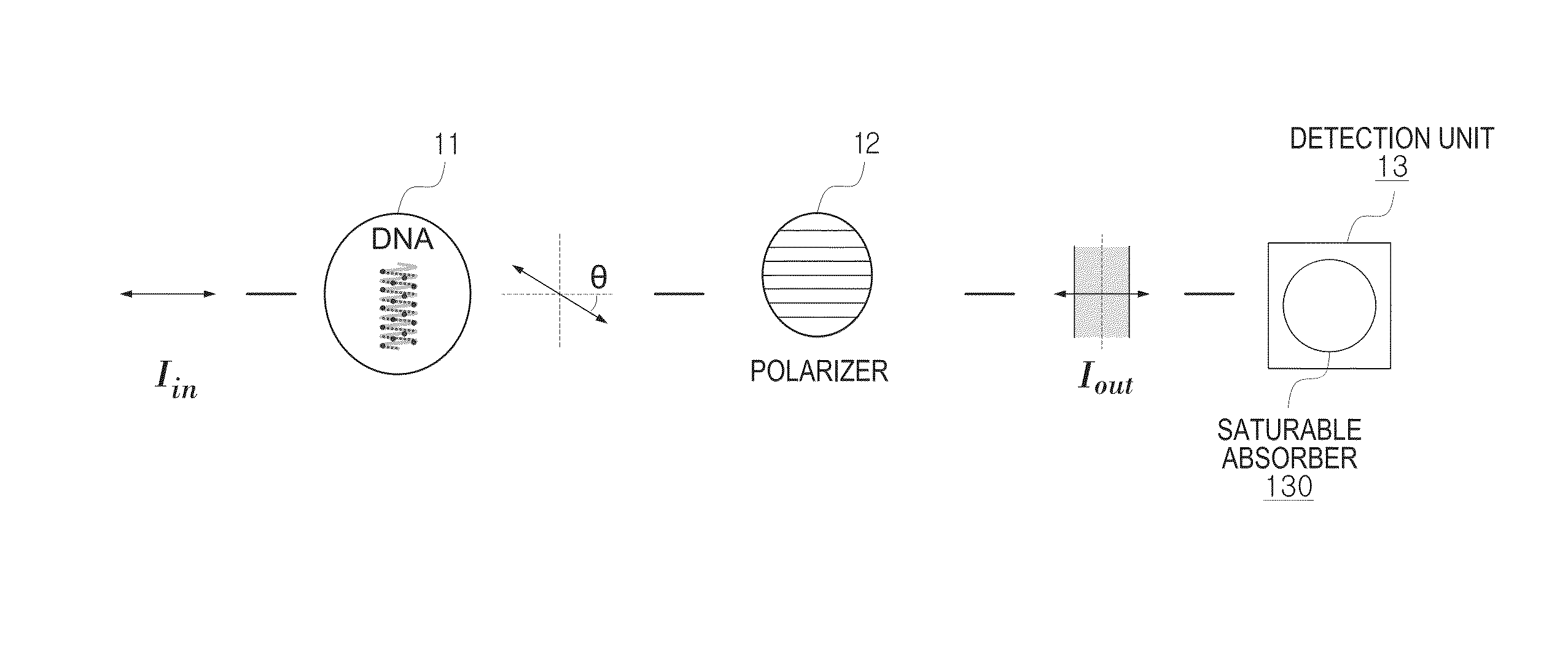
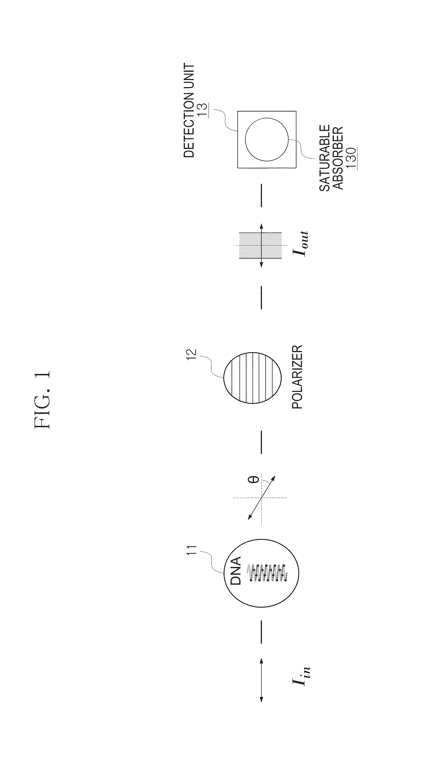
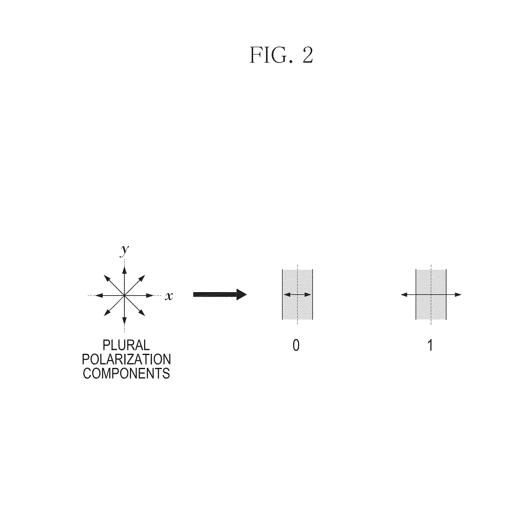
[0023]An optical logic gate according to embodiments disclosed in this specification use a light polarization state as an information delivery medium and is implemented using a polarization plane rotation characteristic of a DNA based nanostructure. In addition, the optical logic gate may be implemented using a transmission characteristic of a saturable absorber according to the intensity of light. The optical logic gate generates a logic signal based on the intensity of light passing through the saturable absorber, and in detail, the logic signal may be determined by comparing the intensity of a component in a specific reference axis direction, which changes according to the degree of rotation of the polarization plane of light, with a predetermined reference value. In an embodiment, the optical logic gate may be configured to...


PUM

PropertyMeasurementUnit
angleaaaaaaaaaa
angleaaaaaaaaaa
rotation angleaaaaaaaaaa

Abstract

An optical logic gate includes: a DNA based nanostructure including DNA and metal nanoparticles coupled to the DNA, the DNA based nanostructure being configured to rotate a polarization plane of an incident light; a polarizer to which light passing through the DNA based nanostructure is incident, the polarizer being configured to extract a component in a direction of a predetermined reference axis from light whose polarization plane is rotated by the DNA based nanostructure; and a detection unit to which light passing through the polarizer is incident, the detection unit being configured to generate a logic signal based on a result obtained by comparing the intensity of the component in the reference axis direction extracted by the polarizer with a predetermined threshold value.

Description

CROSS-REFERENCE TO RELATED APPLICATION[0001]This application claims priority to Korean Patent Application No. 10-2013-0136279, filed on Nov. 11, 2013, and all the benefits accruing therefrom under 35 U.S.C. §119, the contents of which in its entirety are herein incorporated by reference.BACKGROUND[0002]1. Field[0003]Embodiments relate to optical logic gates and a method for generating logic signals using a DNA based nanostructure.[0004]2. Description of the Related Art[0005]A logic circuit (for example, NOT, AND, OR, or the like) refers to a circuit having a function of logically processing numerical information and generating an output. Until now, the logic circuit has been generally implemented based a semiconductor. However, the conventional semiconductor based information processing technique has recently reached the physical limit in its processing rate and degree of integration.[0006]In order to overcome the limit of an available speed of the semiconductor based information pr...

Claims


Application Information

Patent Timeline
Patent Type & Authority Applications(United States)
IPC IPC(8): G02F3/00
CPCG02F3/00Y10S977/941G02B27/286B82Y20/00B82Y10/00G02F2202/36G02F2203/07G02F1/00
Inventor KIM, CHULKIKIM, JAE HUNPARK, BYEONG HOLEE, SEOKJUN, SEONG CHANLEE, TAIKJIN
Owner KOREA INST OF SCI & TECH
Why Eureka
Try Eureka