
Axial turbine

Inactive Publication Date: 2015-05-14
MITSUBISHI HITACHIPOWER SYST LTD
View PDF6 Cites 6 Cited by
  • Summary
  • Abstract
  • Description
  • Claims
  • Application Information

AI Technical Summary

Benefits of technology

The present invention provides an axial turbine that can match the direction of a leakage flow with the main stream, which results in a reduction of mixing loss and a high efficiency in the turbine's operation.

Problems solved by technology

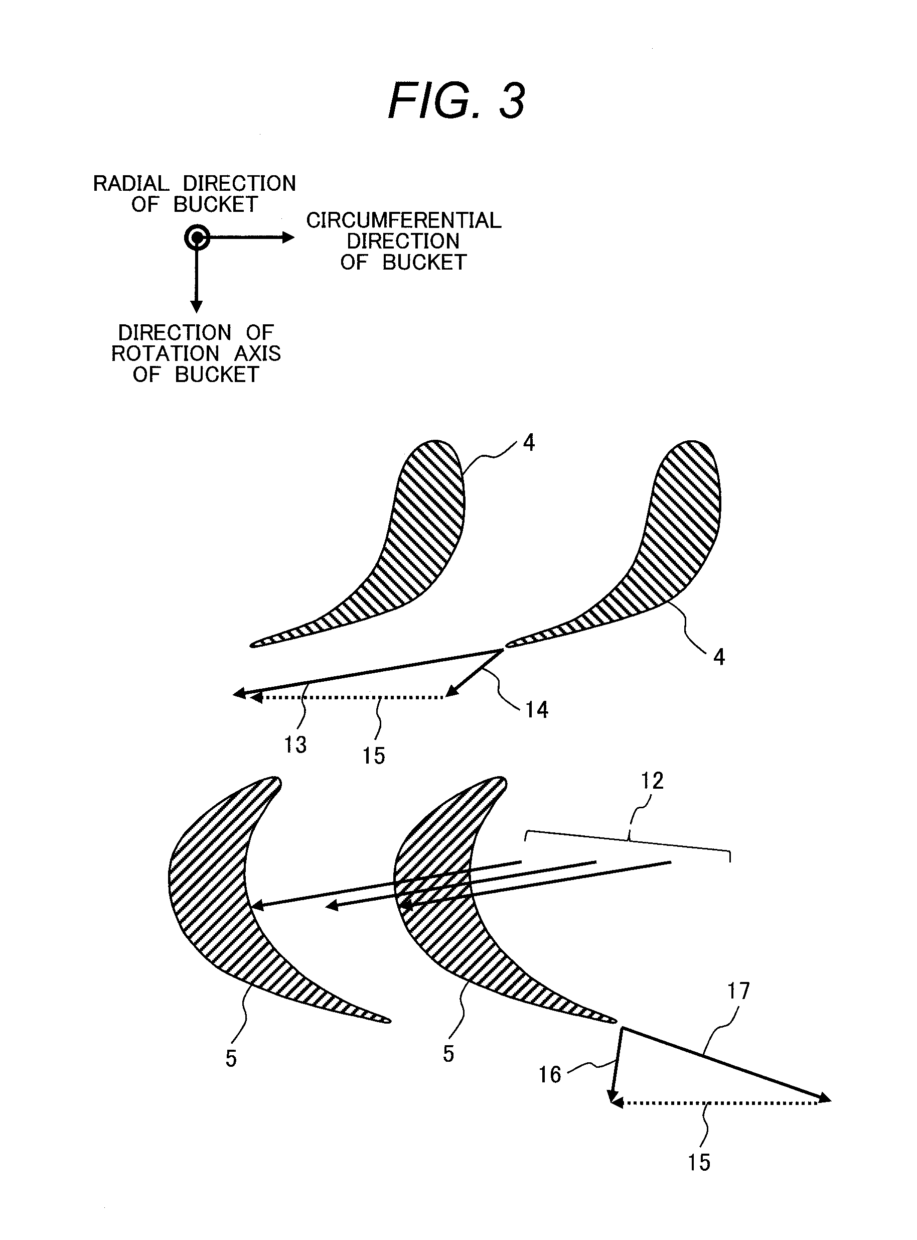
Among those losses, the leakage loss (3) includes (a) a bypass loss caused by a leakage flow passing through a path other than a path for a main stream, thereby preventing effective use of energy held by steam, (b) a mixing loss occurring at the time of a portion of the leakage flow, breaking off a main stream, flowing back into the main stream again, and (c) an incidence loss caused by interference of a portion of the leakage flow, flowing back into the main stream, with downstream cascade of blades.
Incidentally, Patent Literature 1 has not disclosed a relationship between an operation state of the turbine and the guide plate, and there is a possibility that the effect of turning the direction of the leakage flow through the use of the guide plate cannot be sufficiently secured depending on the operation state of the turbine.
In the case where the operation state of the turbine undergoes a change to thereby cause a flow angle of the main stream to change, in particular, an optimum flow angle suitable for installation of the guide plate is changed, and therefore, a mismatch in flow angle between the leakage flow and the main stream is caused to occur as a result of the installation of the guide plate, so that a possibility of fostering the mixing loss contrary to expectations is conceivable.

Method used


Image

  • Axial turbine
  • Axial turbine
  • Axial turbine

Examples


first embodiment

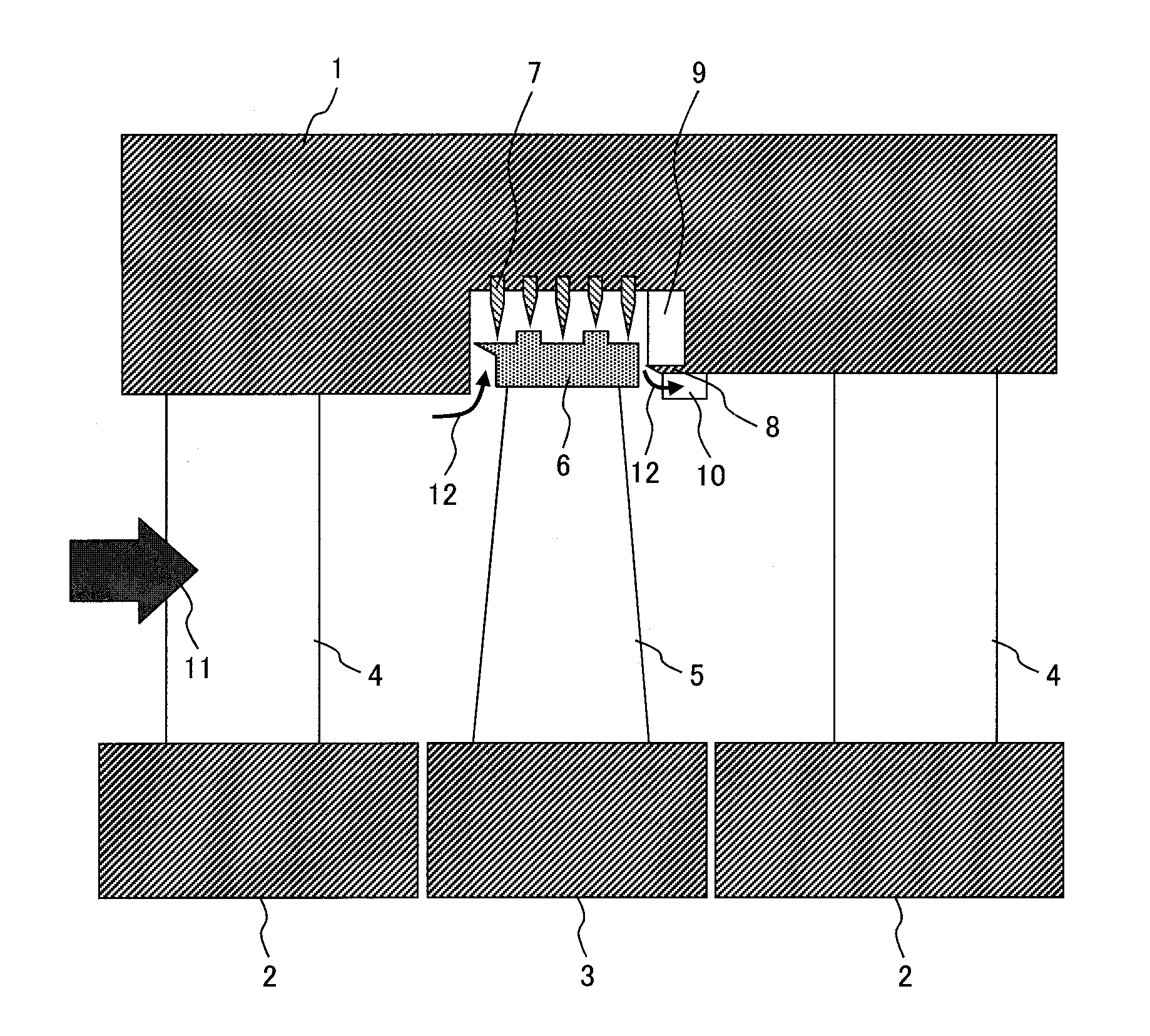
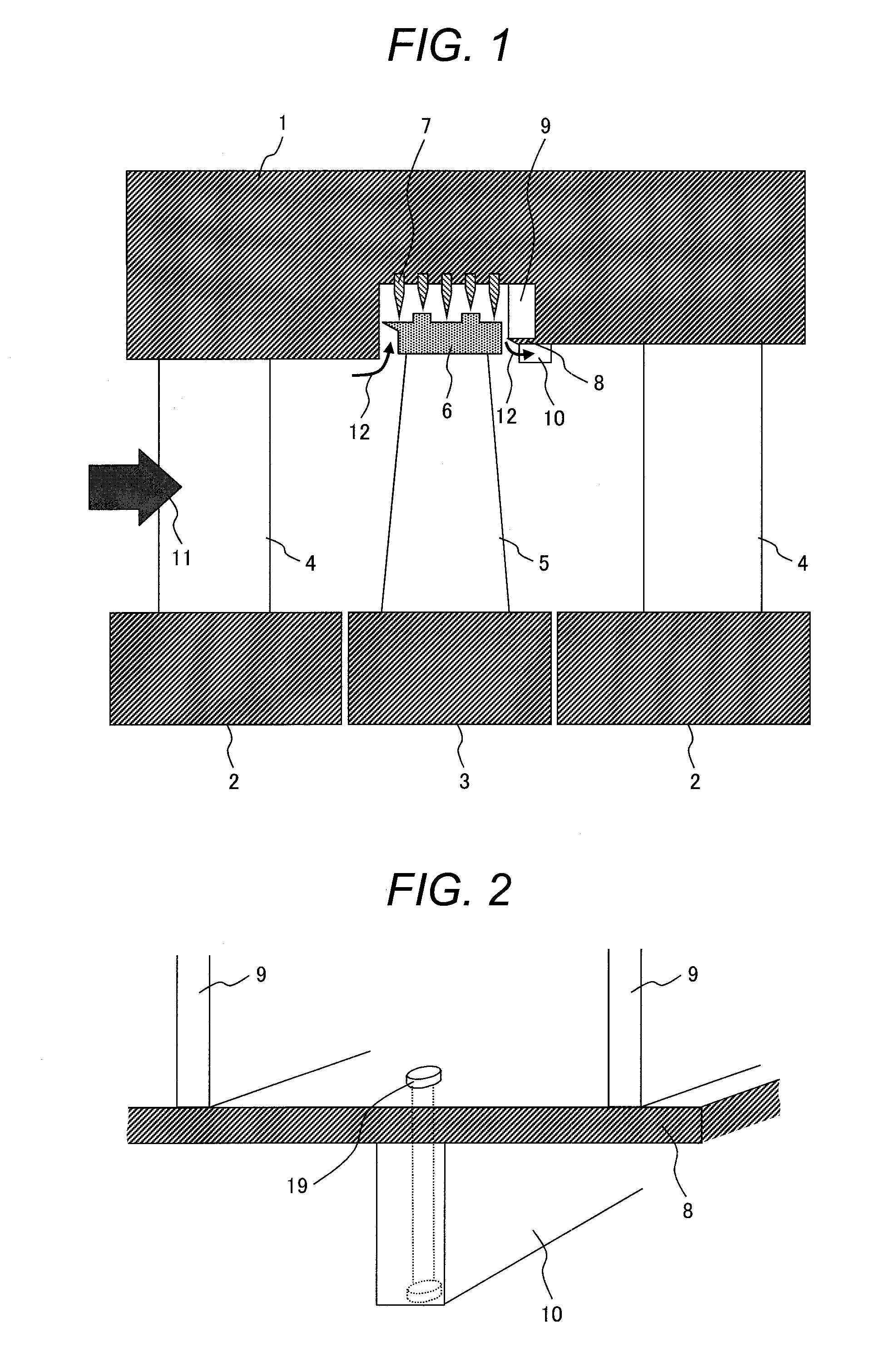
[0024]FIGS. 1 and 2 each show a stage structure of a steam turbine according to a first embodiment of the invention. A turbine-stage of the steam turbine according to the present embodiment is provided with a rotatably supported rotor 3, a bucket 5 fixed to the rotor 3, a shroud 6 provided at the tip of the bucket 5, a diaphragm outer ring 1 opposed to the shroud 6 with a gap provided therebetween, a radial seal fin 7 provided in such a way as to protrude from the diaphragm outer ring 1 in the radial direction of the rotor 3 in a gap between the shroud 6 and the diaphragm outer ring 1, an axial seal fin 8 provided in such away as to protrude from the diaphragm outer ring 1 in the direction of a rotation axis of the rotor 3 in a gap between the shroud 6 and the diaphragm outer ring 1, a plurality of ribs 9 provided in such a way as to be sandwiched between the diaphragm outer ring 1 and the axial seal fin 8 and to be extended from the diaphragm outer ring 1 towards the shroud 6 in th...

second embodiment

[0042]FIGS. 10, and 11 each show a stage structure of a steam turbine according to a second embodiment of the invention. Further, FIG. 12 is a plan view of a guide plate 10 shown in FIG. 11. A turbine stage of the steam turbine according to the present embodiment is provided with a rotatably supported rotor 3, a bucket 5 fixed to the rotor 3, a shroud 6 provided at the tip of the bucket 5, a diaphragm outer ring 1 opposed to the shroud 6 with a gap provided therebetween, a radial seal fin 7 provided in such a way as to protrude from the diaphragm outer ring 1 in the radial direction of the rotor 3 in a gap between the shroud 6 and the diaphragm outer ring 1, an axial seal fin 8 provided in such a way as to protrude from the diaphragm outer ring 1 in the direction of the rotation axis of the rotor 3 in the gap between the shroud 6 and the diaphragm outer ring 1, a plurality of ribs 9 provided in such a way as to be sandwiched between the diaphragm outer ring 1 and the axial seal fin ...


PUM


Abstract

An axial turbine includes a plurality of ribs provided in such a way as to be sandwiched between the diaphragm outer ring and the axial seal fin in the gap between the shroud and the diaphragm outer ring, the ribs being extended from the diaphragm outer ring toward the shroud in the radial direction of the rotor and in the direction of the rotation axis thereof, and a guide plate provided in such a way as to be present along the axial seal fin and a face of the diaphragm outer ring, opposed to the rotor, so as to be extended in the rotation radial direction of the rotor.

Description

CLAIM OF PRIORITY[0001]The present application claims priority from Japanese Patent application serial no. 2013-232039, filed on Nov. 8, 2013, the content of which is hereby incorporated by reference into this application.FIELD OF THE INVENTION[0002]The invention relates to an axial turbine such as a gas turbine and a steam turbine for use in an electric power plant, etc.BACKGROUND OF THE INVENTION[0003]The gas turbine, the steam turbine, etc., for use in the electric power plant, etc., are each broadly classified into three categories on the basis of the flow direction of a working fluid thereof, including an axial turbine with the fluid flowing in the direction of the rotation axis of the turbine, a diagonal turbine with the fluid flowing in such a way as to be diagonally spread from the rotation axis of the turbine, and a radial turbine with the fluid flowing in the radial direction of the turbine. The axial turbine, in particular, among these turbines, is suited for use in an el...

Claims


Application Information

Patent Timeline
IPC IPC(8): F01D11/08
CPCF01D11/08F01D5/145F01D5/225F01D17/162F05D2220/31F05D2250/411F01D17/08F01D17/12F02C7/28F02C9/16
Inventor FUKUSHIMA, HISATAKASHIBATA, TAKANORISEGAWA, KIYOSHILEE, GOINGWON
Owner MITSUBISHI HITACHIPOWER SYST LTD
Learn More