A Double Balanced FET Mixer
A mixer and double-balanced technology, which is applied in the field of microwave and millimeter wave circuits, can solve the problems of high driving power requirements, increased system power consumption and design difficulties, and achieve excellent mixing loss, reduce local oscillator power requirements, and circuit Optimized effect
- Summary
- Abstract
- Description
- Claims
- Application Information
AI Technical Summary
Problems solved by technology
Method used
Image
Examples
no. 1 example
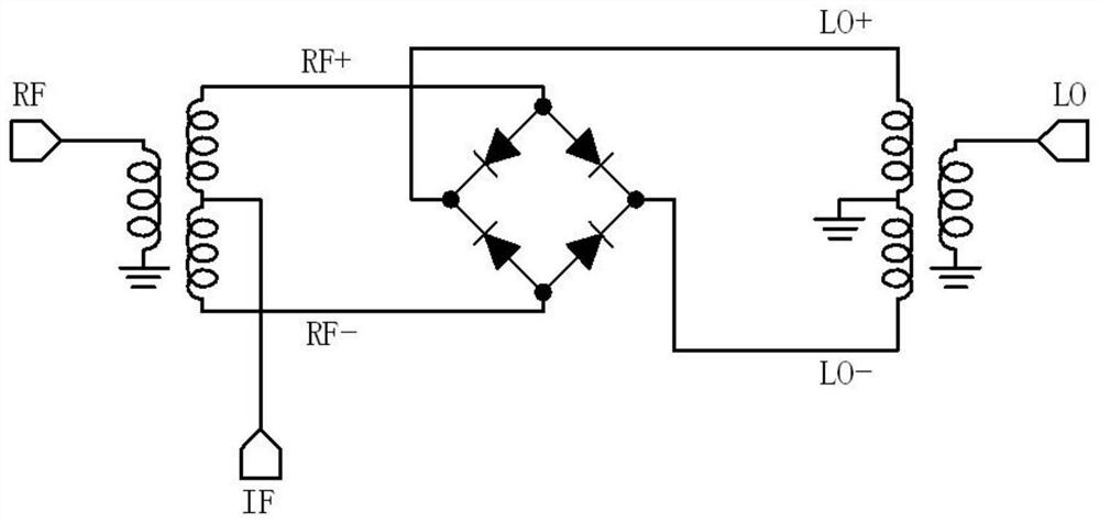
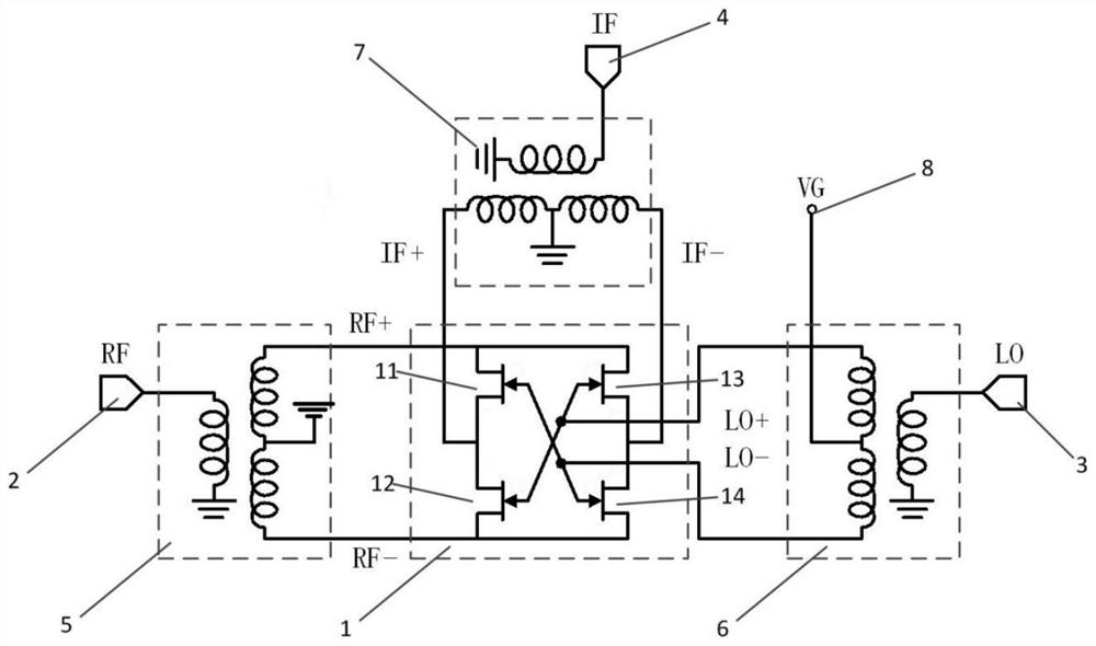
[0040] figure 2 It is a structural schematic diagram of the double-balanced FET mixer of the first embodiment of the present invention. Combine below figure 2 The present invention will be described.
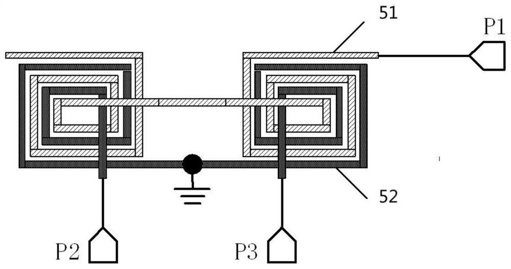
[0041] The double-balanced FET mixer of this embodiment includes a FET ring mixing core 1, a radio frequency signal input terminal 2, a local oscillator signal input terminal 3, an intermediate frequency signal output terminal 4, a first balun 5, a second balun 6, a first balun Three baluns 7 and a bias voltage input terminal 8 . The FET ring mixer core 1 includes a first FET tube 11 , a second FET tube 12 , a third FET tube 13 and a fourth FET tube 14 . The grid of the first FET tube 11 is connected to the grid of the fourth FET tube 14, the drain of the first FET tube 11 is connected to the drain of the second FET tube 12, and the drain of the first FET tube 11 The source is connected to the source of the third FET tube 13 . The gate of the second FET tube 12 is connect...
no. 2 example
[0053] Figure 9 It is a schematic structural diagram of a double-balanced millimeter-wave FET mixer circuit according to the second embodiment of the present invention. Combine below Figure 9 The present invention will be described.
[0054] The double-balanced FET mixer of this embodiment includes a FET ring mixing core 1, a radio frequency signal input terminal 2, a local oscillator signal input terminal 3, an intermediate frequency signal output terminal 4, a first balun 5, a second balun 6, a first balun Three baluns 7 , a first bias voltage input terminal 8 and a second bias voltage input terminal 9 . The FET ring mixer core 1 includes a first FET tube 11 , a second FET tube 12 , a third FET tube 13 and a fourth FET tube 14 . The grid of the first FET tube 11 is connected to the grid of the fourth FET tube 14, the drain of the first FET tube 11 is connected to the drain of the second FET tube 12, and the drain of the first FET tube 11 The source is connected to the ...
no. 3 example
[0063] Figure 12 It is a schematic structural diagram of the quadrature mixer circuit of the third embodiment of the present invention, combined below Figure 12 to Figure 14 The present invention will be described.
[0064] according to Figure 12 The quadrature mixer in this embodiment shown includes a radio frequency input terminal 100, and a radio frequency signal is input to a radio frequency quadrature coupler 101 through the radio frequency input terminal 100, and the radio frequency quadrature coupler 101 outputs two signals to two identical structures. A double-balanced FET mixer 102, the double-balanced FET mixer 102 uses the double-balanced FET mixer described in one of the foregoing first to third embodiments. The local oscillator signal is input to the power divider 104 through the local oscillator signal input terminal 103, and the two-way local oscillator signal is output by the power divider 104 to the two identical double-balanced FET mixers 102, and the tw...
PUM
 Abstract
Description
Claims
Application Information
 - R&D
- Intellectual Property
- Life Sciences
- Materials
- Tech Scout
- Unparalleled Data Quality
- Higher Quality Content
- 60% Fewer Hallucinations
Browse by: Latest US Patents, China's latest patents, Technical Efficacy Thesaurus, Application Domain, Technology Topic, Popular Technical Reports.
© 2025 PatSnap. All rights reserved.Legal|Privacy policy|Modern Slavery Act Transparency Statement|Sitemap|About US| Contact US: help@patsnap.com


