Adaptive maximum intermediate frequency energy tracking radar receiving system

A technology of receiving system and tracking radar, which is applied in the direction of radio wave measurement system, measurement device, radio wave reflection/reradiation, etc. It can solve the problem of affecting the radar's ability to detect small targets, increasing the safety hazards of ships, and deviating from fixed frequencies, etc. problem, to achieve the effect of improving reliability and scalability, short conversion time, and overcoming spectrum changes

Active Publication Date: 2015-12-02
上海广电通信技术有限公司
View PDF7 Cites 10 Cited by
  • Summary
  • Abstract
  • Description
  • Claims
  • Application Information

AI Technical Summary

Problems solved by technology

[0003] At present, marine navigation radar generally uses radar magnetron as the microwave power amplifier device of the radar transmitter. Since the transmission frequency of the magnetron will change with time and temperature, this makes the optimal center frequency point after down-conversion deviate from a fixed Frequency, if the radar receiving system cannot track the frequency change of the magnetron, it is better to stabilize the best tracking frequency at a fixed frequency. At this time, the radar intermediate frequency echo is not in the best tuning position, and the echo energy will weaken, affecting the radar The ability to detect small targets increases the safety hazards of ships sailing

Method used


Image

  • Adaptive maximum intermediate frequency energy tracking radar receiving system
  • Adaptive maximum intermediate frequency energy tracking radar receiving system
  • Adaptive maximum intermediate frequency energy tracking radar receiving system

Examples


Embodiment

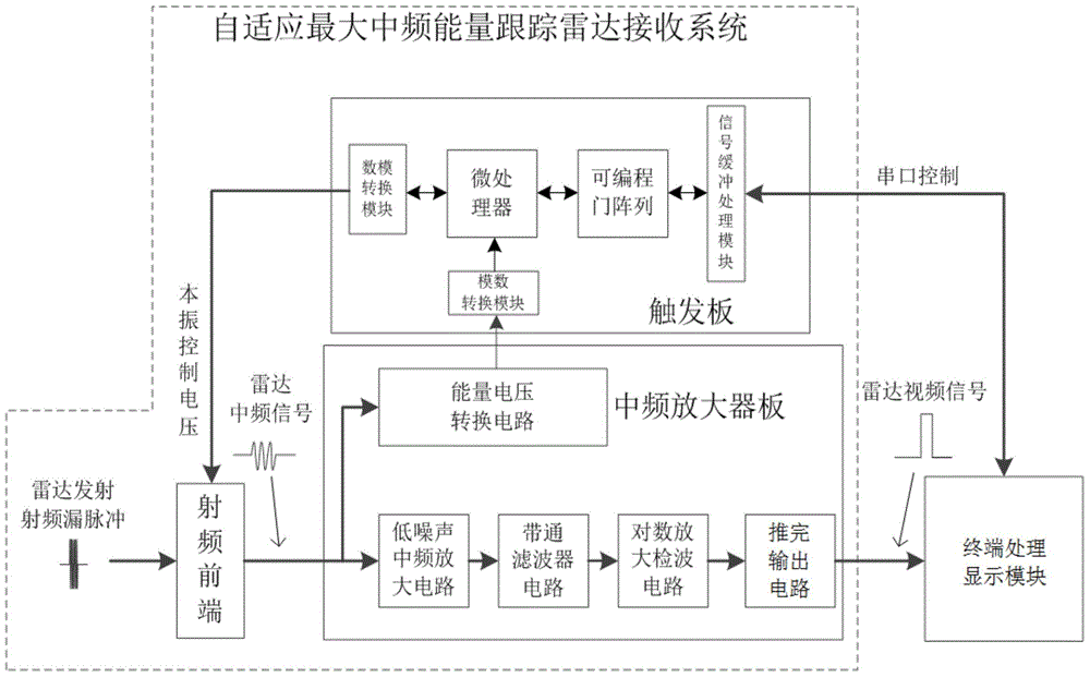
[0023] Such as figure 1 As shown, in the dotted line frame among the figure is the adaptive maximum intermediate frequency energy tracking radar receiving system of the present invention, comprises radio frequency front end, trigger board, intermediate frequency amplifier board, is connected by cable between radio frequency front end and intermediate frequency amplifier board, each of trigger board The circuit signal is connected to the IF amplifier board through a cable, and the trigger board is connected to the radar terminal through a serial cable.

[0024] The RF front-end includes low-noise amplifiers, double-balanced mixers, and local oscillators.

[0025] The trigger board includes a microprocessor, a programmable gate array, a signal buffer processing module, an analog-to-digital conversion module, and a digital-to-analog conversion module. The trigger board is the control center of the entire adaptive maximum intermediate frequency energy tracking radar receiving syst...


PUM


Abstract

The invention discloses an adaptive maximum intermediate frequency energy tracking radar receiving system, and the system comprises a radio frequency front end, a triggering board, an intermediate frequency amplifier board, and a radar terminal. The radio frequency front end comprises a low-noise amplifier, a double-balance frequency mixer, and a local oscillator. The triggering board comprises a microprocessor, a programmable gate array, a signal buffering processing module, an analog-digital conversion module, and a digital-analog conversion module. The intermediate frequency amplifier board comprises an energy voltage conversion circuit, a low-noise intermediate frequency amplification circuit, a band-pass filter circuit, a logarithmic amplification detection circuit, and a push output circuit. The radar terminal comprises a terminal processing display module. The invention provides a brand-new receiving system based on maximum intermediate frequency energy tracking, completely changes a mode of automatic frequency control of a conventional navigation radar receiving system, and effectively solves a problem that a conventional mode of frequency tracking causes the decrease of capability of finding a small object because of the frequency spectrum change of a radar transmitter magnetron. The digitalization of the radar receiving system improves the reliability and expansibility of the radar receiving system.

Description

technical field [0001] The patent of the present invention relates to the technical field of non-coherent marine navigation radar, specifically, an adaptive maximum intermediate frequency energy tracking radar receiving system. Background technique [0002] Marine navigation radar is mainly used for detection and tracking of maritime targets, assisting ship navigation and collision avoidance, and ensuring navigation safety. With the increasing complexity of the ship's navigation environment, the performance of navigation radar is directly related to the safety of the ship's navigation and the safety of the people on board. [0003] At present, marine navigation radar generally uses radar magnetron as the microwave power amplifier device of the radar transmitter. Since the transmission frequency of the magnetron will change with time and temperature, this makes the optimal center frequency point after down-conversion deviate from a fixed Frequency, if the radar receiving sys...

Claims


Application Information

Patent Timeline
Patent Type & Authority Applications(China)
IPC IPC(8): G01S7/285G01S7/41G01S13/88G01S13/93
CPCG01S7/285G01S7/411G01S13/88G01S13/937
Inventor 金凌王文瀚刘晓辉王亚年陈华桥周文明陶梦文李进
Owner 上海广电通信技术有限公司
Why Eureka
Try Eureka