
Control device for controlling a safety device, and use of an IO link for transmission of a safety protocol to a safety device

a control device and safety technology, applied in the field of machine and plant engineering, can solve the problems of inability to use high-performance bus systems in an economically viable manner on the sensor/actuator level, the cost of work hours and the material required for the installation of hardware for signal transmission to the machine exceeds the installation space of mechanical handling systems, and the cost of work for the installation of hardware for signal transmission to the machine exceeds the purchasing cost of connected binary sensors and actuators. , to achieve the effect of reducing

Active Publication Date: 2015-05-14
BALLUFF
View PDF11 Cites 7 Cited by
  • Summary
  • Abstract
  • Description
  • Claims
  • Application Information

AI Technical Summary

Benefits of technology

The control device described in this patent allows for the transmission of a safety protocol through an audio link connection, eliminating the need for additional cabling. This provides a more efficient and cost-effective solution for ensuring the safety of the system.

Problems solved by technology

In many assembly facilities the space requirements for the cabling / wiring and the switch box for the electrical installation often exceeds the installation space of the mechanical handling system.
Almost always the costs for the work hours and the material required for the installation of the hardware for signal transmission to the machine exceed the purchasing costs of the connected binary sensors and actuators.
However, it is a problem and disadvantage that it is practically impossible to use these high-performance bus systems in an economically viable manner on the sensor / actuator level.
Field-bus-based solutions are available on the market, but they are comparatively complex.
What is frequently found is a parallel wiring of safe signals, which, however, involves a high expenditure of labor and often results in a confusingly complex cabling systems.
Besides, there are also safety devices having a medium complexity which need to be parameterized.

Method used


Image

  • Control device for controlling a safety device, and use of an IO link for transmission of a safety protocol to a safety device
  • Control device for controlling a safety device, and use of an IO link for transmission of a safety protocol to a safety device
  • Control device for controlling a safety device, and use of an IO link for transmission of a safety protocol to a safety device

Examples


Embodiment Construction

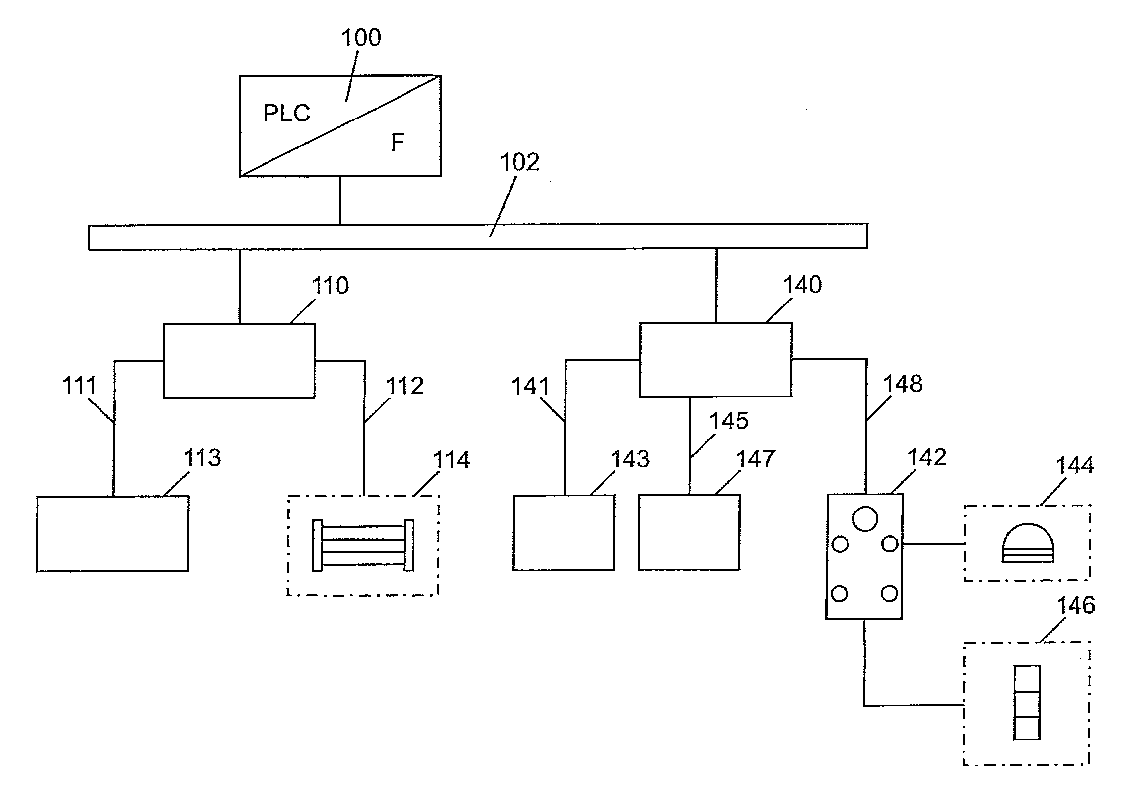
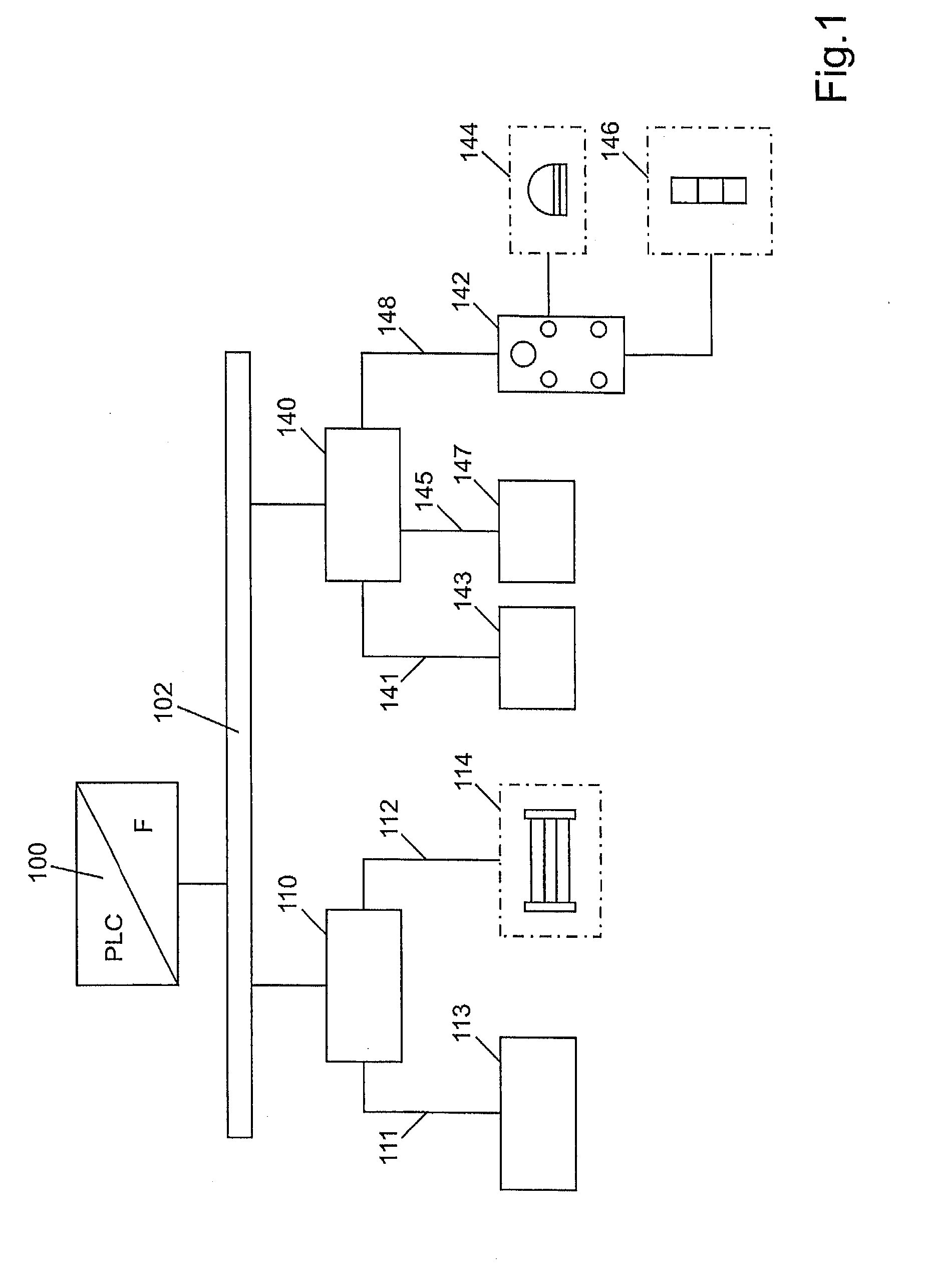
[0025]FIG. 1 schematically shows a control device for controlling terminal devices that are realized in the form of IO link devices. A central control device, a controller 100, is embodied as a PLC (programmable logic control), for one thing, and, for another thing, as a F control device (fail safe control device). This means that the controller 100 is able to control ordinary terminal devices as well as safety devices, or it can process their data. Master assemblies 110, 140 are connected to this central controller 100 via a field bus 102, wherein an IO link device 113, which is not relevant with regard to safety, i.e. which is not a safety device, is connected via an IO link connection 111. Further, a safety device 114, for example a light curtain, a light grid, a transceiver, a light barrier, a laser scanner etc., is connected via an IO link connection 112. FIG. 1 shows a schematic representation of a light curtain. This light curtain can be arranged in a safety-relevant area of ...


PUM


Abstract

A control device for controlling a safety device which can be connected to a master assembly by means of an IO link is characterized in that a safety protocol can be transmitted via an IO link connection.

Description

[0001]The invention relates to a control device for controlling a safety device according to claim 1. Further, the invention relates to the use of an IO link for transmitting a safety protocol from a master assembly to a safety device.STATE OF THE ART[0002]In the field of machinery and plant engineering as well as in automation engineering numerous standardized field bus systems have proven to provide good alternatives to parallel individual wiring. Here, a plurality of so-called field bus modules is connected to a central control device via a field bus. In turn, terminal devices are connected to the field bus modules. More recently, IO link connections have been used for connecting the terminal devices to the field bus modules. When this is done, the field bus modules take over the function of the IO link master. Terminal devices can be sensors, actuators, display devices, operator devices or smaller drives in machines, for example. In many assembly facilities the space requirement...

Claims


Application Information

Patent Timeline
Patent Type & Authority Applications(United States)
IPC IPC(8): G06F13/12G06F13/42
CPCG06F13/4221G06F13/122G05B19/0425G06F13/126
Inventor FEINAEUGLE, ALBERT
Owner BALLUFF
Learn More