
Basin

a technology of natural stone countertops and integrated pools, which is applied in the field of basins, can solve the problems of not being able to match, neither of the sinks made from these materials matches the distinct properties of the countertop, and the sinks made from these materials do not typically yield basins that match. the effect of lessening the depth of the basin

Inactive Publication Date: 2015-05-21
CASEY MICHAEL
View PDF6 Cites 2 Cited by
  • Summary
  • Abstract
  • Description
  • Claims
  • Application Information

AI Technical Summary

Benefits of technology

The present invention is a basin or sink made from high-end countertops. The stones used in the basin are cut with a special angle and depth, resulting in the shapes of the basin having larger perimeters on the outside and smaller perimeters on the inside. The bottom of the basin has a circular hole for draining water. The cut stones are stacked together, maintaining their original positions and relationships. The result is a basin that matches the patterning of the original slab, with minimal changes. The basin can be affixed to the original slab or other slab, and can be used as a drop-in sink or an integrated basin. The invention allows for the creation of a custom-made basin that matches the countertop being installed. The technical effect of the invention is the production of a basin with minimal alterations to its patterning, allowing for aesthetically pleasing and custom-made installations.

Problems solved by technology

In the case of natural stone, the patterning or veining of each slab is often unique and not readily matched.
None of the sinks made from these materials match the distinct properties of the countertop.
Neither of these methods typically yields a basin that matches the distinct properties of the countertop.
Additionally, when a hole is cut in the slab to integrate the basin, the piece of slab removed becomes remnant material that is greatly devalued because of its smaller contiguous size; and therefore fewer practical applications.

Method used


Image

  • Basin
  • Basin
  • Basin

Examples


first embodiment

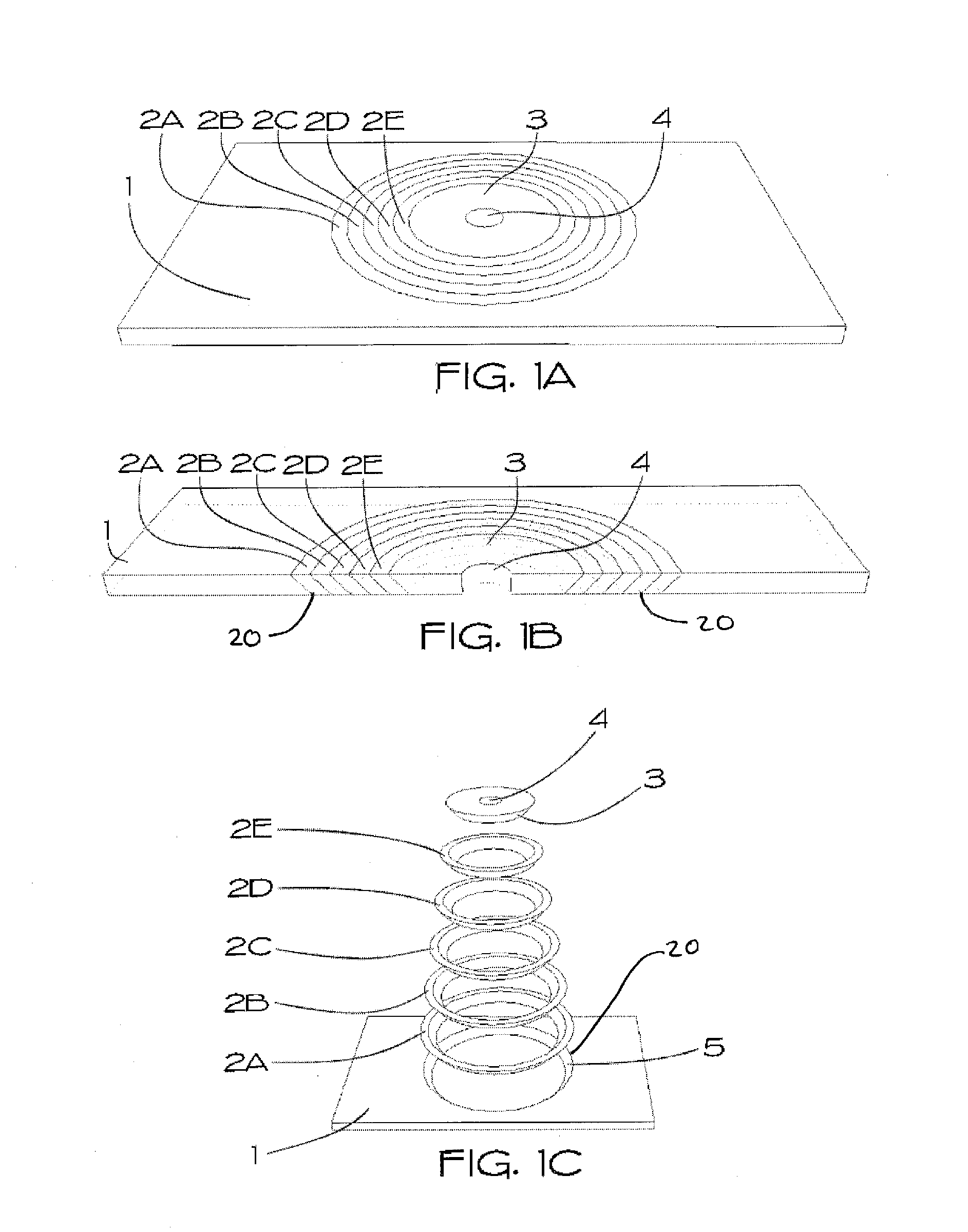
[0041]FIGS. 1A, 1B, and 1C comprise three views of the invention.

[0042]FIG. 1A is a top-front perspective view of an embodiment of a solid slab 1 of natural or other solid surface countertop material 1 in which concentric conic section rings 2 with cut at an angle 20 through the slab 1 towards the center 2A-2E have been cut. Interior to the innermost conic section ring 2E, a disc 3 is cut with outer edge angled toward the center in a supplementary manner to the innermost edge of the innermost conic section ring 2E. In the center of the disc 3 a cylindrical hole 4 is cut.

[0043]FIG. 1B is a cross-section of a top-front view of the embodiment of FIG. 1A highlighting the angles of the cuts of the circular conic section rings 2A-2E through the slab 1. Also displayed is interior disc 3 with cylindrical hole 4.

[0044]FIG. 1C is a top-front perspective of an exploded view of the embodiment in FIG. 1 showing the rings 2: concentric conic section rings 2A-2E; interior disc 3 with cylindrical h...

second embodiment

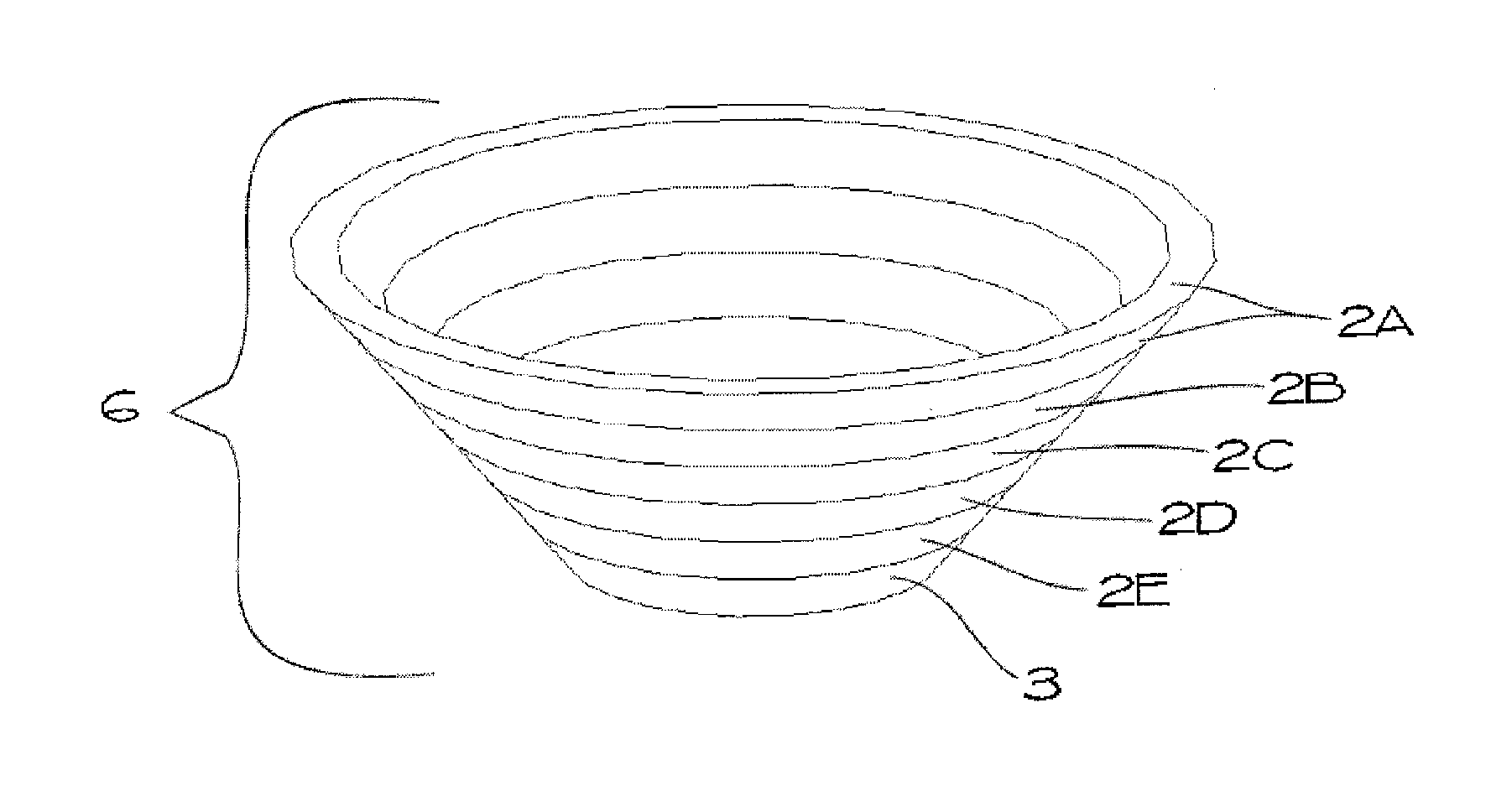
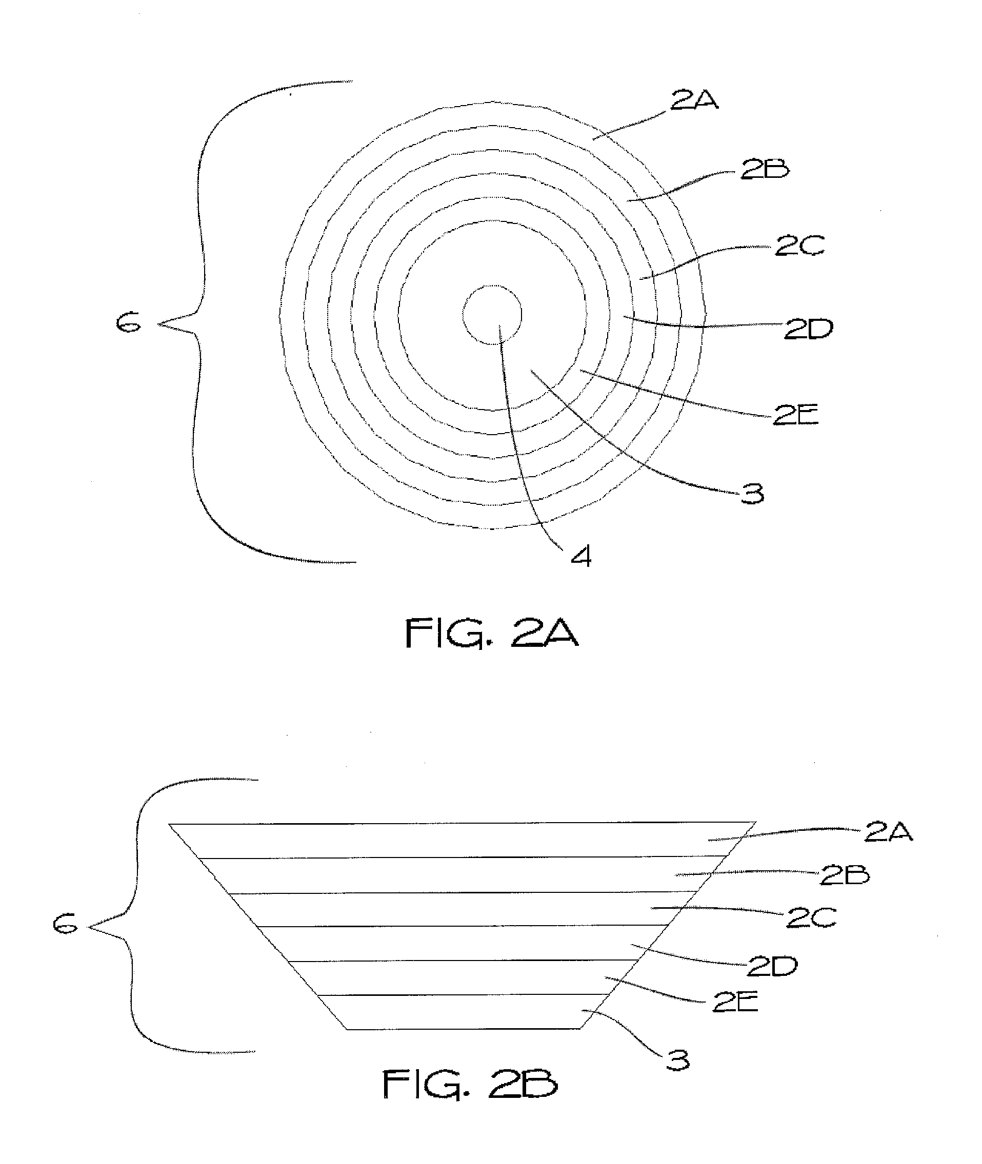
[0054]FIGS. 4A and 4B comprise two views of an embodiment of a completed second embodiment of the invention, wherein the assembled basin 6 is lowered into the cavity 27 into the slab 1, rather than being mounted to the underside as in FIGS. 3A, 3B, and 3C. This embodiment represents what is commonly known as a “drop-in” basin in the art.

[0055]FIG. 4A is a top-front perspective view of the basin 6 being lowered into the cavity 27 in the slab 1. The interior angled cut 5 of slab 1 is the same slope as and aligns with the exterior of basin 6.

[0056]FIG. 4B is a top-front perspective of a completed embodiment of the invention, wherein the rim of basin 6 is flush with the top surface 28 of the slab 1. The hidden inner edge 5 of slab 1 (shown in FIG. 4A) is flush with and affixed to the outer edge of basin 6.

third embodiment

[0057]FIG. 5 comprises two views of a completed third embodiment of the invention, wherein the basin 6 is affixed to a different slab 7. The slab 7 used in this embodiment is necessarily different from the original slab 1 (FIGS. 1A, 1B, and 1C) because it must not have a cavity 27 like the one caused by removal of rings 2A-2F and 3 (FIGS. 1A, 1B, and 1C). The slab 7 has a hole 30 cut in it to facilitate a drain. This embodiment is commonly known in the art as a “vessel” style basin.

[0058]FIG. 5A is a top-front perspective view of a vessel embodiment of the invention, wherein the bottom of basin 6 is affixed to the top surface 28 of slab 7.

[0059]FIG. 5B is a bottom-front view of the embodiment in FIG. 5A, wherein the bottom of basin 6 is affixed to the top surface 28 of slab 7.

[0060]FIG. 6 is a top-front perspective view of an embodiment of the invention wherein the basin 6 is affixed to a different slab 8 to form a drop-in sink with high overhanging rim. The slab 8 used in this embo...


PUM

PropertyMeasurementUnit
angleaaaaaaaaaa
angleaaaaaaaaaa
angleaaaaaaaaaa

Abstract

A basin manufactured from a solid slab of stone having a depth of multiple times the thickness of the original slab, which may match the naturally occurring patterns of said slab when used as a countertop, and a method of producing the same.

Description

[0001]This patent application claims is the benefit of U.S. Provisional Patent Application No. 61 / 904,686 having a filing date of 15 Nov. 2013.BACKGROUND OF THE INVENTION[0002]1. Technical Field[0003]The invention is generally related to the field of natural (or artificial) stone countertops and integrated pooling sinks: specifically under-mount, top mount (vessel), and drop-in sinks. This invention is also related to the reuse of “remnant” stone material typically devalued when the hole is cut in the slab in order to place a basin. Additionally, this invention relates to the field of custom stonework, where the item produced incomparably matches the grain and patterning of another piece made from the same unique stone.[0004]2. Related Art[0005]High-end stone countertops are known for their beauty, ease of maintenance, and (depending on material) durability. The fact that large portions, if not the entirety, of these countertops are formed from a single slab of stone adds to these c...

Claims


Application Information

Patent Timeline
Patent Type & Authority Applications(United States)
IPC IPC(8): E03C1/18B28D1/22
CPCB28D1/22E03C1/18B28D1/02B28D1/30Y10T29/49796
Inventor CASEY, MICHAEL
Owner CASEY MICHAEL
Learn More