Eureka AIR delivers breakthrough ideas for toughest innovation challenges, trusted by R&D personnel around the world.

Hydraulic energy conversion device

Active Publication Date: 2015-05-21
NAT CHUNG SHAN INST SCI & TECH
View PDF13 Cites 4 Cited by
  • Summary
  • Abstract
  • Description
  • Claims
  • Application Information

AI Technical Summary

Benefits of technology

The present invention provides a hydraulic energy conversion device for mounting in a hydraulic shock absorber to convert the hydraulic energy of the hydraulic shock absorber into mechanical energy without hindering its normal operation. The device can be mounted inside the hydraulic shock absorber and used to replace conventional shock absorbers of the same size. The device converts the vibration energy of the hydraulic fluid in the shock absorber into a rotary mechanical energy which can be used to drive a generator to output electric power. The device can be used in electric vehicles but also in general internal combustion engine vehicles to recycle vibration energy and achieve the same effect.

Problems solved by technology

However, the typical vane-type hydraulic motor is enclosed in a complicated cast case with the shaft exposed from the case, and has radially oriented hydraulic fluid inlets and outlets and a fixing plate provided on one side thereof.
That is, the use of the conventional vane-type hydraulic motor to replace the damping valve would occupy an additional space in the vehicle and could not be directly used to replace the conventional tube-shaped shock absorber.

Method used


Image

  • Hydraulic energy conversion device
  • Hydraulic energy conversion device
  • Hydraulic energy conversion device

Examples


Embodiment Construction

[0013]The present invention will now be described with a preferred embodiment thereof and by referring to the accompanying drawings. One of ordinary skill in the art can easily understand the advantages and effects of the present invention from the description below.

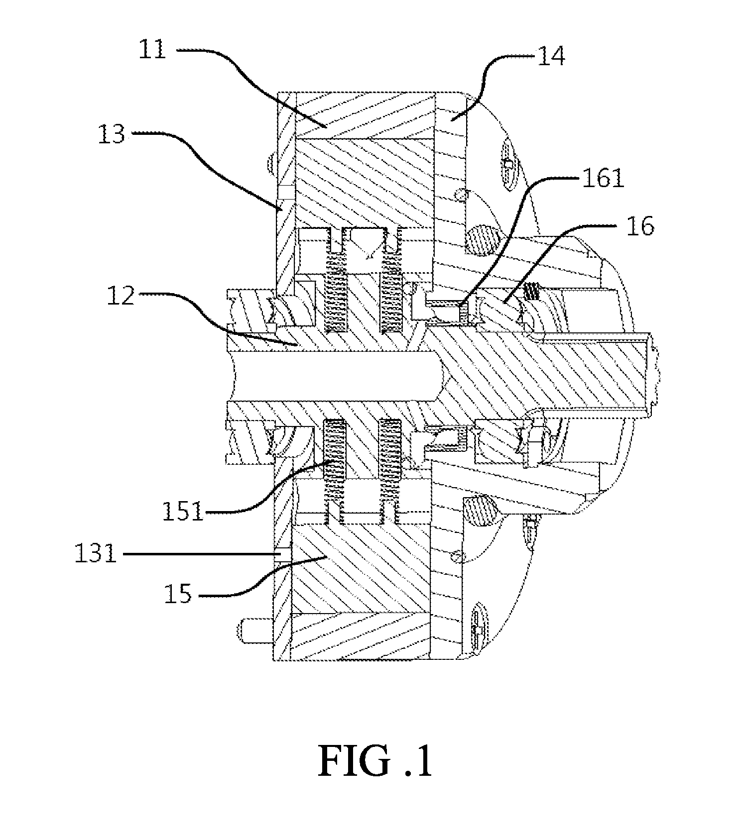
[0014]Please refer to FIG. 1 that is a longitudinal sectional view showing the structure of a hydraulic energy conversion device according to a preferred embodiment of the present invention. As shown, the hydraulic energy conversion device includes a main body 11, which is an annular member having a central hole; an output shaft 12, which is mounted in the central hole of the main body 11 with a centerline extended perpendicular to the central hole; a fixing plate 13, which is located at an end of the main body 11 and provided with a plurality of passage holes 131; an outer cover 14, which is located at another end of the main body 11 opposite to the fixing plate 13 and has a central opening, via which the output shaft 1...


PUM


Abstract

A hydraulic energy conversion device includes a main body being an annular member having a central hole, an output shaft mounted in the central hole of the main body with a centerline extended perpendicular to the central hole; a fixing plate located at an end of the main body and provided with a plurality of passage holes; an outer cover located at another end of the main body opposite to the fixing plate and having a central opening for the output shaft to outwardly extended through the outer cover; and a plurality of vanes circumferentially spaced on the output shaft to locate in a space defined between the main body, the fixing plate and the outer cover. The hydraulic energy conversion device is mounted in a hydraulic shock absorber to convert hydraulic energy into mechanical energy and output the same without hindering the hydraulic shock absorber from normal operation.

Description

CROSS-REFERENCE TO RELATED APPLICATION[0001]This non-provisional application claims priority under 35 U.S.C. §119(a) on Patent Application No(s). 102141970 filed in Taiwan, R.O.C. on Nov. 19, 2013, the entire contents of which are hereby incorporated by reference.FIELD OF THE INVENTION[0002]The present invention relates to an energy conversion technique, and more particularly to a hydraulic energy conversion device for use with a shock absorber or a damping device to recycle the hydraulic energy thereof.BACKGROUND OF THE INVENTION[0003]Being affected by many severe events involving oil crisis and air pollution in recent years, it has become an inevitable trend for all kinds of traffic and transportation means to use energy-saving and environment-friendly parts. For internal combustion engine vehicles, only a small part of the power output by the internal combustion engine thereof is use to run the vehicles while other part is offset by various kinds of resistance. One example of suc...

Claims


Application Information

Patent Timeline
IPC IPC(8): B60G13/14H02K7/00
CPCH02K7/003B60G13/14F16F9/32F03B13/00F16F9/10F05B2220/60Y02B10/50
Inventor CHEN, CHUEN-ANCHEN, CHE-PINTUNG, CHIEHYEH, TE-MINGSHIH, MIN-HUA
Owner NAT CHUNG SHAN INST SCI & TECH
Why Eureka
Eureka Blog
Learn More