Hydraulic shock absorber

a technology of shock absorber and shock absorber, which is applied in the direction of shock absorbers, mechanical equipment, transportation and packaging, etc., can solve the problems of deterioration of rust degrades the bump cushion itself, and the air cannot escape from the inside properly, so as to prevent deterioration or degradation of durability and improve the durability of the bump cushion

Inactive Publication Date: 2005-11-10
KYB CORP
View PDF7 Cites 25 Cited by
  • Summary
  • Abstract
  • Description
  • Claims
  • Application Information

AI Technical Summary

Benefits of technology

[0010] It is an object of the present invention to provide a hydraulic shock absorber in which a bump cushion is not contacted to a piston rod to prevent deterioration or degradation of durability caused by the sliding of the bump cushion and the piston rod, and air inside the bump cushion at the time of the bumping of a cylinder escapes more properly to improve durability of the bump cushion.

Problems solved by technology

As a result, plating on the outer periphery of the piston rod comes off during a long term use, flaws are produced thereon, rust occurs thereon to damage durability of the piston rod, and the rust degrades the bump cushion itself.
And as the inner periphery of the bump cushion contacts the piston rod as described above, when the upper portion of the cylinder bumps on the bump cushion to compress the bellows type of the tubular portion, air inside the bump cushion is also compressed, but this air does not escape from the inside properly to deteriorate durability of the bump cushion due to air pressures repeatedly applied during a long term use.

Method used


Image

  • Hydraulic shock absorber
  • Hydraulic shock absorber
  • Hydraulic shock absorber

Examples


Embodiment Construction

[0015] The selected embodiment of the present invention will now be explained with reference to the drawings. It will be apparent to those skilled in the art from this disclosure that the following description of the embodiment of the present invention is provided for illustration only, and not for the purpose of limiting the invention as defined by the appended claims and their equivalents.

[0016] A preferred embodiment of the present invention will be explained with reference to the drawings.

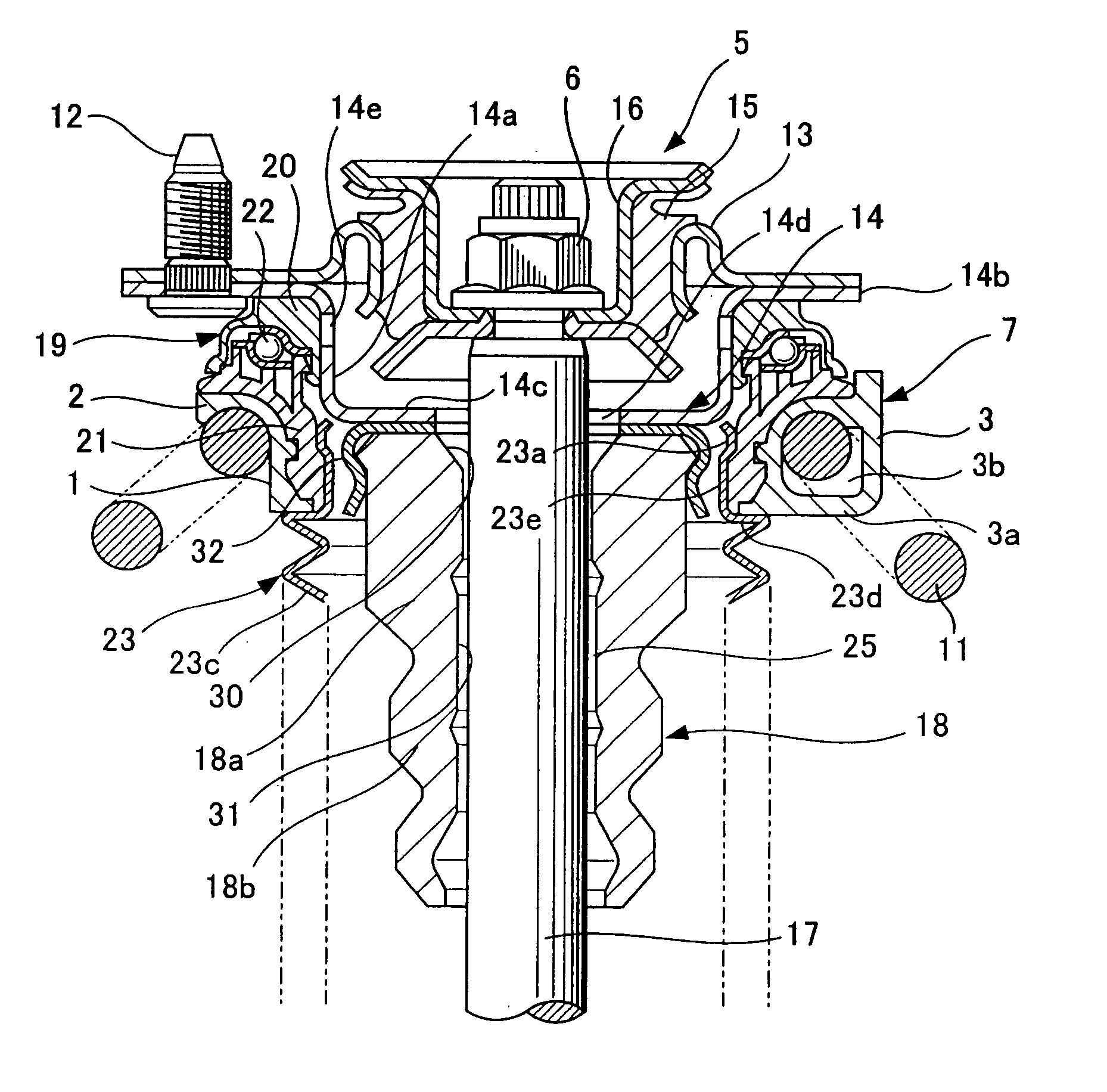
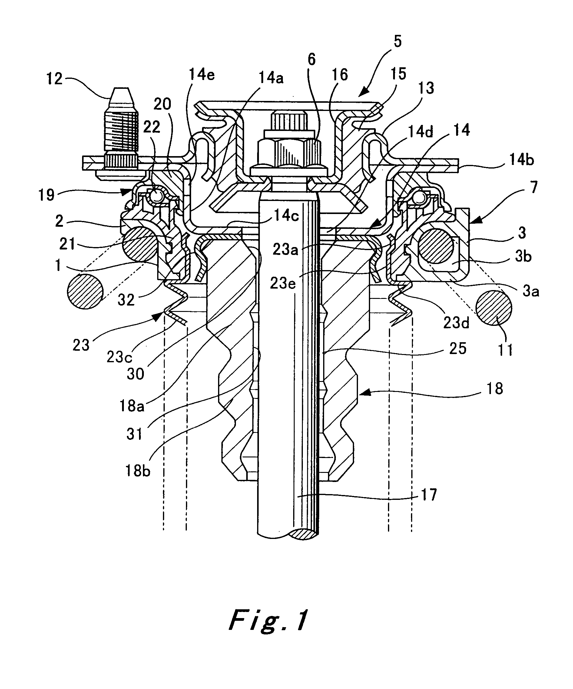
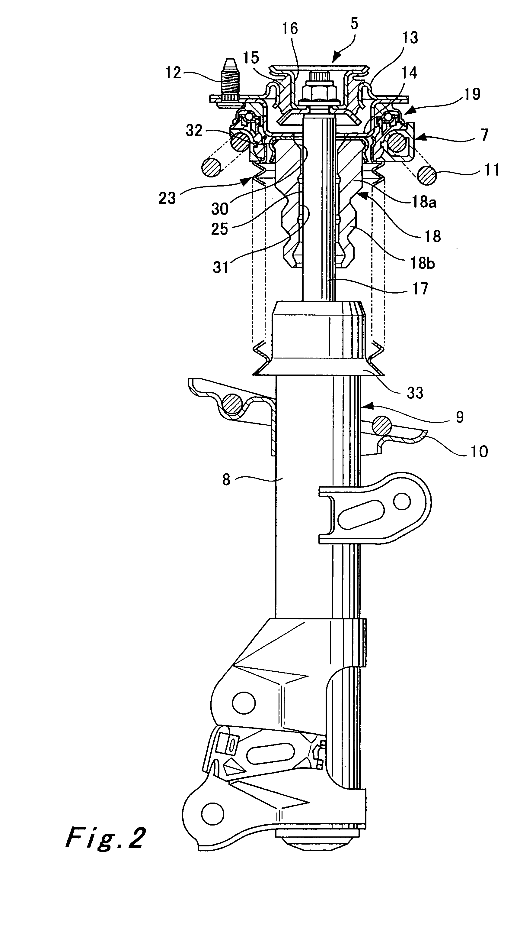
[0017] As shown in FIG. 1 and FIG. 2, an upper portion of a shock absorber 9 is coupled to a vehicle body mount 5. In detail, a piston rod 17 extends from a cylinder 8 of the shock absorber 9 so that the piston rod 17 expands from and contracts into the cylinder 9, and a top end of the piston rod 17 is coupled to the vehicle body mount 5.

[0018] The vehicle body mount 5 is provided with an inner base 13 connected to a side of a vehicle body via bolts 12, a cover 14 fastened together to a lowe...


PUM


Abstract

A bump cushion (18) is inserted and fixed in an outer periphery of an upper portion of a piston rod (17) connected to a vehicle body mount (5), and the bumping of the upper portion of a cylinder (8) on the bump cushion (18) at the time of the compression operation absorbs the jolts. A circular clearance (25) is all the time formed between an inner periphery of the bump cushion (18) and an outer periphery of the piston rod (17) and the clearance (25) is communicated with an outside.

Description

BACKGROUND OF THE INVENTION [0001] 1. Field of the Invention [0002] The present invention relates to a hydraulic shock absorber used as a suspension for a vehicle, and in particular, to an improvement in a structure of a bump cushion (bump rubber) disposed in an upper portion of a piston rod. [0003] 2. The Related Art of the Invention [0004] In general a hydraulic shock absorber used as a suspension for a vehicle is interposed between a side of a vehicle body and a side of a vehicle axle, and is provided with a tubular bump cushion in an upper portion of a piston rod coupled to a vehicle body mount. At the time of a compression operation of the shock absorber, especially in the neighborhood of the maximum compression an upper portion of the cylinder is designed to bump on the bump cushion to provide cushioning, thus preventing jolt transmission from the side of the vehicle axle to the side of the vehicle body. [0005] A mounting structure of the bump cushion is disclosed in, for exam...

Claims


Application Information

Patent Timeline
Patent Type & Authority Applications(United States)
IPC IPC(8): F16F9/54F16F9/58
CPCF16F9/58B60G2204/45021
Inventor OOTA, AKIHISA
Owner KYB CORP
Why Eureka
Try Eureka