A new type of rotating drive system for mixing drum of concrete mixer truck

A mixer truck, rotary drive technology, applied in cement mixing devices, clay preparation devices, chemical instruments and methods, etc., can solve the problems of destroying the quality of commercial concrete, excessive exhaust gas, and large energy consumption, and avoid inefficiencies. The effect of long-term work, not too expensive, and improved economy

Inactive Publication Date: 2011-12-14
SICHUAN UNIV
View PDF8 Cites 27 Cited by
  • Summary
  • Abstract
  • Description
  • Claims
  • Application Information

AI Technical Summary

Problems solved by technology

During the conveying process of the concrete mixer truck, the engine not only drives the mixer truck but also drives the rotation of the mixer drum, so the engine works under a large load, but when the mixer truck stops and only the mixer drum rotates at a low speed or When the transport vehicle returns empty, only a small part of the power of the engine is needed, so for a large part of the working time, the engine works at the inefficient point
[0039] For the traditional hydraulic-mechanical hybrid driving scheme, when the mixer truck is transporting concrete, the driving speed of the whole vehicle is constantly changing due to different road conditions, which causes the stirring speed of the mixing drum to fluctuate, which makes the concrete in the drum The uneven flow will damage the quality of commercial concrete and reduce the dynamic characteristics of the walking system. A lot of energy is used to change the inertia of the mixing drum, wasting a lot of fuel
In addition, the thermal efficiency of the automobile engine is very low, and it needs to consume a lot of energy during work. Even when the engine is idling, it must meet the rotation requirements of the mixing drum. When the engine speed is too high, a higher speed will waste a lot of unnecessary energy. energy loss
The cost of the electronic constant speed solution is relatively high, and the hydraulic constant speed solution will waste a considerable amount of energy at the throttle port that controls the constant speed, resulting in excessive exhaust emissions, polluting the environment, and driving operations. Safety hazards and a host of other issues

Method used


Image

  • A new type of rotating drive system for mixing drum of concrete mixer truck
  • A new type of rotating drive system for mixing drum of concrete mixer truck
  • A new type of rotating drive system for mixing drum of concrete mixer truck

Examples


specific Embodiment approach 1

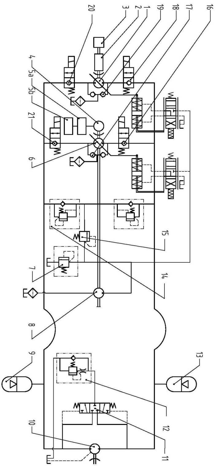
[0087] Such as figure 1 As shown, a new type of concrete mixer truck mixing drum rotation drive system. This scheme is based on the traditional single pump-motor closed circuit acceleration and deceleration scheme, adding a small displacement hydraulic main pump to form a double pump parallel closed circuit to drive the hydraulic motor and transmit power through the hydraulic motor to the reducer, and then the reducer drives the mixing drum. The small-displacement hydraulic main pump is driven by a small-power independent prime mover power system, and the high-power prime mover power system drives a large-displacement hydraulic main pump. The oil inlet and outlet of the large and small-displacement hydraulic main pumps are connected in parallel. The high-power prime mover power system mainly includes: the chassis engine 3 is connected to the servo variable pump 1 through the power take-off 2 (or the servo variable pump 1 is directly driven by an independent high-power engine...

specific Embodiment approach 2

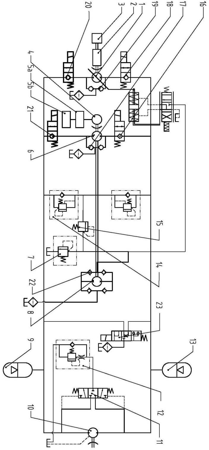
[0094] Such as figure 2 As shown, the main components and connections of the high-power prime mover power system are the same as the first scheme; the high-power prime mover can be a chassis engine, an independent high-power electric motor or an independent high-power engine. The low-power prime mover power system here is the electric motor power system, mainly including: battery 5b, motor controller 5a, independent small-power motor 4, two-way quantitative pump 6, oil charge pump 8, two-position two-way electromagnetic or electro-hydraulic reversing valve 16, 21 and the bridge circuit 22 composed of one-way valves drive the two-way quantitative hydraulic motor 10; the battery 5b controls the independent small-power motor 4, the two-way quantitative pump 6 and the charge pump through the motor controller such as the frequency converter 5a 8 can be selected to be connected with the same axis. Also in order to reduce the influence of the system pressure on the two-way quantitat...

specific Embodiment approach 3

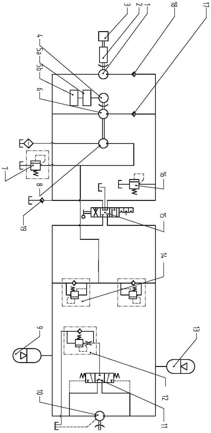
[0100] Such as image 3 As shown, the high-power prime mover power system refers to the chassis engine power system or a high-power independent prime mover power system such as a high-power independent engine or a high-power independent electric motor drive system. When the high-power prime mover is a chassis engine, the chassis engine power system mainly includes: chassis engine 3, power take-off 2, one-way quantitative pump 1, one-way valve 18, chassis engine 3 is connected to quantitative pump 1 through power take-off 2 , in order to reduce the influence of system pressure on the large-displacement main pump 1, a check valve 18 is installed at the outlet of the large-displacement quantitative pump 1; when the high-power prime mover is an independent high-power engine, the independent high-power engine power system It mainly includes: an independent high-power engine, a quantitative pump 1, and a check valve 18. The independent high-power engine is connected to the quantitat...


PUM


Abstract

The invention relates to a novel rotation driving system for a mixing drum of a concrete mixing transport vehicle. In the system, two prime movers, two hydraulic main pumps, an oil supply pump and a hydraulic motor form a hydraulic closed loop together with a hydraulic valve block with the functions of relatively completing oil supply, cooling and safe buffering; the delivery volumes of the two hydraulic main pumps are different; and the low-delivery volume hydraulic main pump is used for separately realizing slow and constant mixing action of the mixing drum, and the high-delivery volume hydraulic main pump is used for rotating the mixing drum along positive and negative directions at a high speed during feeding and discharging when separately operated or combined with the low-delivery volume hydraulic main pump. The system aims to solve the problems of the influence on the concrete uniformity and the influence on the driving dynamic performance and driving safety performance which are caused by driving a roller to rotate by separately using a chassis engine under different working conditions and different road conditions in the mixing drum, fuel waste caused by the long-term operation of the high-power chassis engine at low-efficiency points and the hydraulic shock generated during the switching of the mixing drum under different working conditions.

Description

technical field [0001] The invention relates to a novel rotary driving system for a mixing drum of a concrete mixing transport vehicle. Background technique [0002] The background technology of this patent is explained by taking the industry standard of concrete mixer truck and the implementation scheme of the rotating drive system of the mixing drum (hereinafter referred to as the mixing drum) of conventional concrete mixer truck as examples. In the automotive industry standard QC / T667-2000 "Technical Conditions for Concrete Mixer Trucks" (hereinafter referred to as "Technical Conditions") drafted by Zhai Yanhua, Shuai Guoju and others: [0003] It is required in Article 4.1.8: the maximum allowable time for the transport vehicle from feeding to conveying and unloading is 90 minutes, and the continuous operation of the mixing drum is not more than 300 revolutions according to the regulations; when mixing, the maximum speed of the vehicle shall not exceed 50 km / h; [000...

Claims


Application Information

Patent Timeline
Patent Type & Authority Applications(China)
IPC IPC(8): B28C5/42
Inventor 韩嘉骅赫磊姚进
Owner SICHUAN UNIV
Why Eureka
Try Eureka