Automobile hydraulic shock absorber

a hydraulic shock absorber and hydraulic technology, applied in the direction of shock absorbers, wound springs, transportation and packaging, etc., can solve the problems of difficult to set the damping force to the optimum value, the overall length of the shock absorber is increased by an amount proportional to the required space, and the shock cannot be dampened in such cases, etc., to achieve the effect of light weight and small overall length

Active Publication Date: 2011-05-26
YAMAHA MOTOR CO LTD
View PDF11 Cites 26 Cited by
  • Summary
  • Abstract
  • Description
  • Claims
  • Application Information

AI Technical Summary

Benefits of technology

[0037]As a result, through various preferred embodiments of the present invention, an automobile hydraulic shock absorber can be provided having a small overall length and light

Problems solved by technology

Small bumps on the road over which the vehicle wheel rolls during travel are insufficient to cause the piston of the hydraulic shock absorber to move in relation to the cylinder body, and shocks that occur in such cases cannot be dampened.
The hydraulic shock absorber disclosed in WO 2004/065817 therefore has drawbacks in that the overall length thereof is increased by an amount commensurate with the required space.
It is ther

Method used


Image

  • Automobile hydraulic shock absorber
  • Automobile hydraulic shock absorber
  • Automobile hydraulic shock absorber

Examples


first preferred embodiment

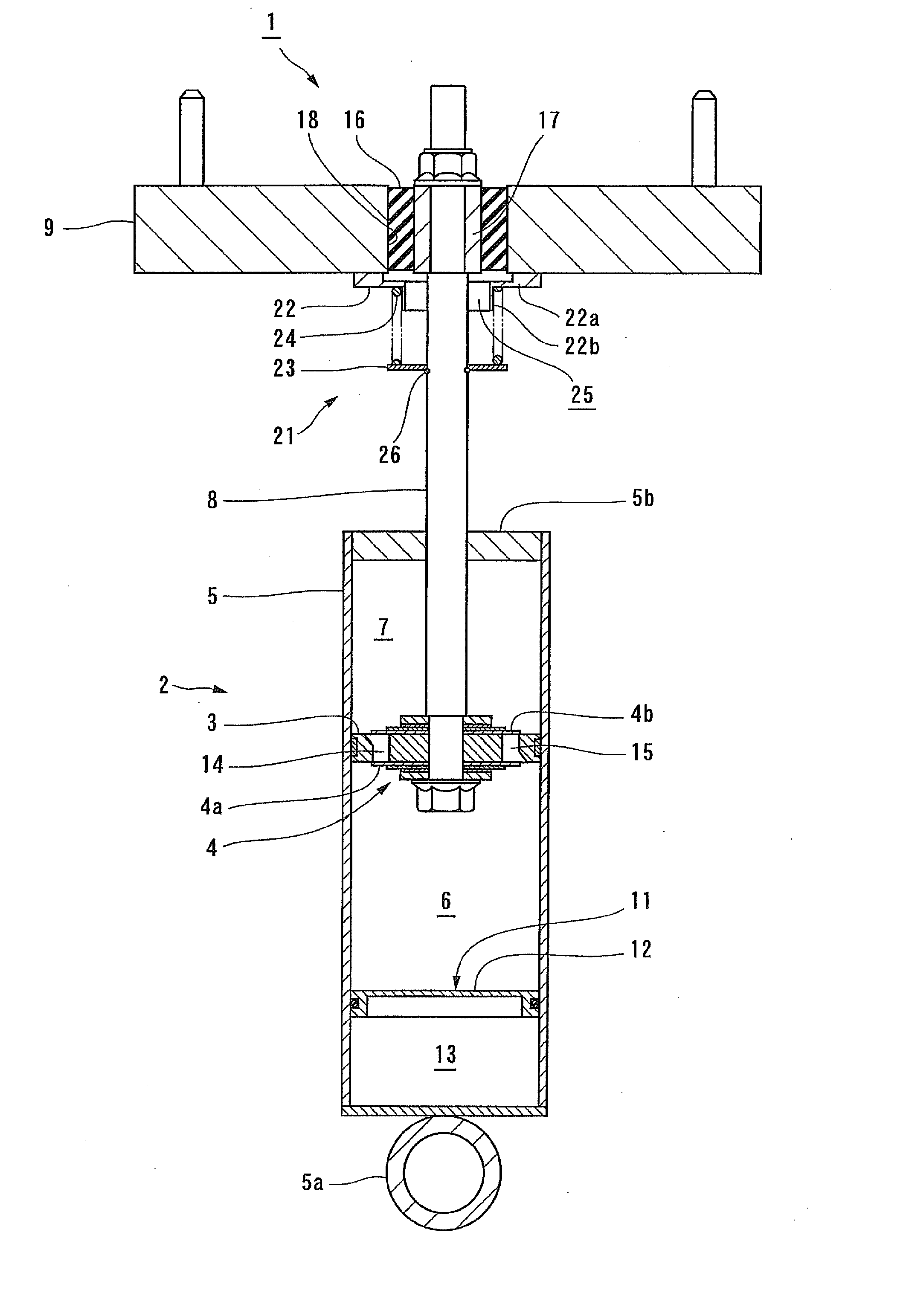
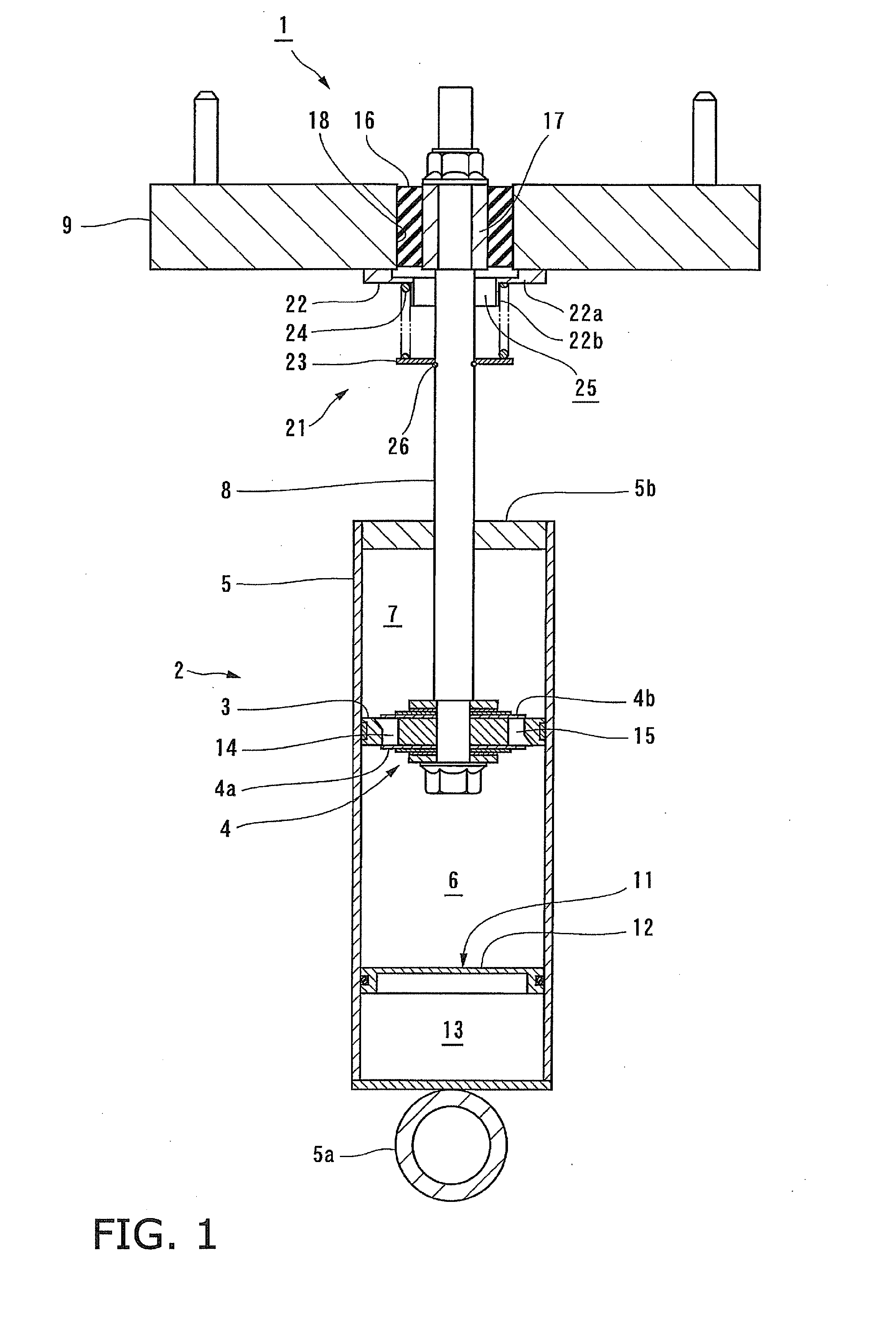
[0052]A first preferred embodiment of the automobile hydraulic shock absorber of the present invention will be described in detail according to FIG. 1.

[0053]The hydraulic shock absorber 1 shown in FIG. 1 is provided between the vehicle body and a wheel of an automobile. The hydraulic shock absorber 1 preferably includes a hydraulic cylinder 2, a diaphragm 4 provided to a piston 3 of the hydraulic cylinder 2, and other components.

[0054]The hydraulic cylinder 2 preferably includes a cylinder body 5, the piston 3, a piston rod 8, and other components. The bottom end portion of the cylinder body 5 is connected to the vehicle wheel. The piston 3 divides the inside of the cylinder body 5 into a first oil chamber 6 on the bottom end side and a second oil chamber 7 on the top end side. The piston rod 8 is connected to the piston 3. The inside of the first oil chamber 6 and the inside of the second oil chamber 7 are filed with operating oil. The hydraulic cylinder 2 according to the present ...

second preferred embodiment

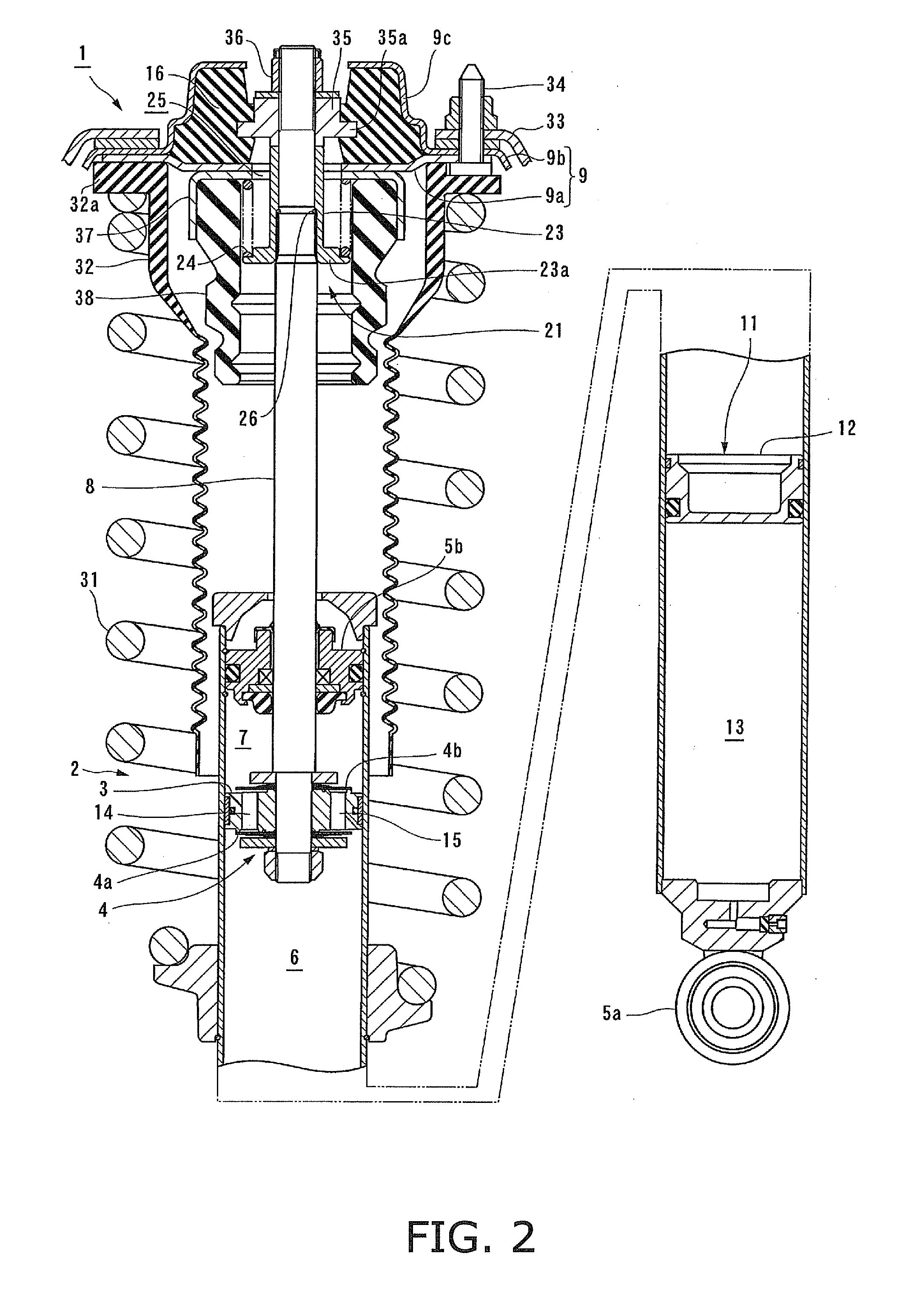
[0083]The automobile hydraulic shock absorber according to a second preferred embodiment of the present invention can be formed as shown in FIG. 2. In FIG. 2, the same reference numerals are used to refer to members that are the same as or equivalent to those described in FIG. 1, and no detailed description of such members will be given.

[0084]The cylinder body 5 shown in FIG. 2 is inserted into a damping spring 31 to support the weight of the vehicle body. The damping spring 31 is provided between the cylinder body 5 and the upper support 9.

[0085]In the present preferred embodiment, an attachment flange 32a of a rubber cover 32 is held between the upper support 9 and the top end portion of the damping spring 31. The rubber cover 32 covers the top portion of the hydraulic cylinder 2.

[0086]The upper support 9 according to the present preferred embodiment preferably includes a lower plate 9a, and an upper plate 9b which is placed over the lower plate 9a. The upper support 9 is fixed to...

third preferred embodiment

[0092]The pressure-applying mechanism can be configured as shown in FIGS. 3A and 3B. In FIGS. 3A and 3B, the same reference numerals are used to refer to members that are the same as or equivalent to those described in FIGS. 1 and 2, and no detailed description of such members will be given.

[0093]A supporting bracket 41 shaped so as to cover the top end portion of the piston rod 8 is attached to the upper support 9 shown in FIGS. 3A and 3B. The supporting bracket 41 preferably has a cup shape which opens downward. The supporting bracket 41 is fixed to the frame member 33 by a fixing bolt 34 together with the upper support 9 so as to cover the upper support 9 from above.

[0094]The pressure-applying mechanism 21 is attached to the supporting bracket 41 via a pushing force adjustment mechanism 42 described hereinafter. In other words, the pressure-applying mechanism 21 according to the present preferred embodiment is provided above the upper support 9 (on the opposite side of the shock ...


PUM


Abstract

An automobile hydraulic shock absorber includes a cylinder body, a piston, an upper support, a piston rod, a volume adjustment mechanism, first and second communicating passages, and a pressure-applying mechanism. The piston rod is attached to the upper support via a rubber cushion. The volume adjustment mechanism includes a free piston. The first and second communicating passages communicate the first oil chamber and second oil chamber with each other in the cylinder body via a diaphragm. The pressure-applying mechanism is disposed outside the cylinder body, movement thereof is restricted by the upper support, and the pressure-applying mechanism pushes the piston rod downward.

Description

BACKGROUND OF THE INVENTION[0001]1. Field of the Invention[0002]The present invention relates to an automobile hydraulic shock absorber provided between the vehicle body and the wheels of an automobile.[0003]2. Description of the Related Art[0004]A conventional automobile hydraulic shock absorber is composed of a hydraulic cylinder, and a diaphragm or the like provided to the hydraulic cylinder to generate a damping force (see WO 2004 / 065817, for example). The hydraulic cylinder of the hydraulic shock absorber described in WO 2004 / 065817 is provided with a cylinder body, a piston, and a piston rod. The piston divided inside of the cylinder body into a first oil chamber at the bottom-end side, and second oil chamber at the top-end side. The piston is attached to the piston rod.[0005]The bottom end portion of the cylinder body is attached to a vehicle wheel via a rubber cushion. The piston rod passes through the top end portion of the cylinder body to protrude above the cylinder body....

Claims


Application Information

Patent Timeline
IPC IPC(8): F16F9/06
CPCF16F9/065F16F9/54F16F9/067
Inventor KONDOU, KATSUHIROMAEDA, MASASHIYAMAZAKI, YUTAKA
Owner YAMAHA MOTOR CO LTD
Why Eureka
Try Eureka