Method of closed form release for brittle materials using burst ultrafast laser pulses

a technology of ultrafast laser pulses and closed forms, applied in glass making apparatus, manufacturing tools, welding/soldering/cutting articles, etc., can solve problems such as damaged/unusable released forms

Active Publication Date: 2015-05-21
ROFIN SINAR TECH
View PDF5 Cites 107 Cited by
  • Summary
  • Abstract
  • Description
  • Claims
  • Application Information

AI Technical Summary

Benefits of technology

[0008]The general purpose of the present invention, which will be described subsequently in greater detail, is to pro...

Problems solved by technology

The problem with many of these methods is that they either leave:
Obviously, all of these ...

Method used


Image

  • Method of closed form release for brittle materials using burst ultrafast laser pulses
  • Method of closed form release for brittle materials using burst ultrafast laser pulses
  • Method of closed form release for brittle materials using burst ultrafast laser pulses

Examples


Embodiment Construction

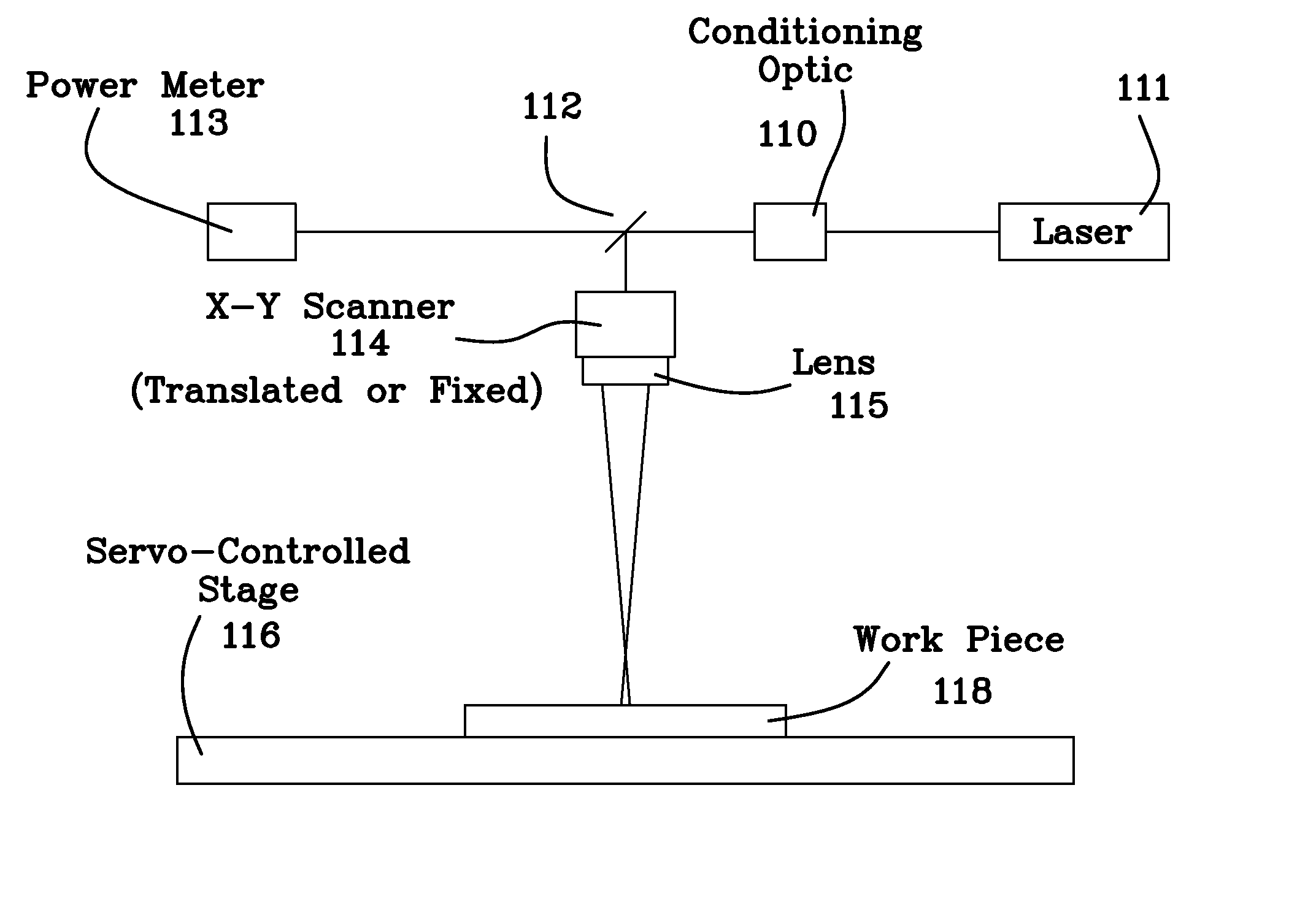
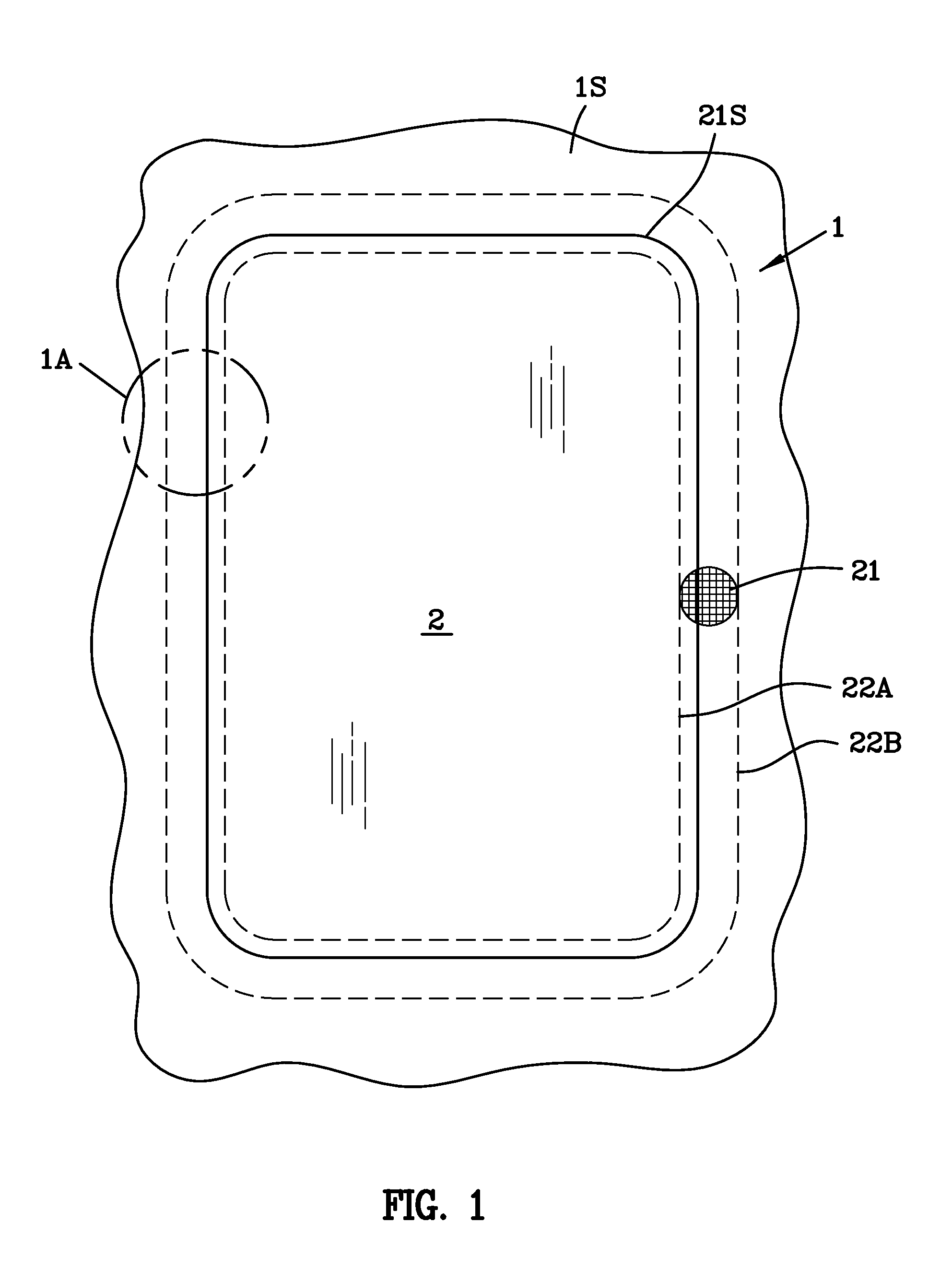
[0032]Transparent materials especially, but not limited to the families of glass, are common substrates from which closed forms are cut. A common example would be the intricate closed form configuration in transparent material target and may be selected from the group consisting of transparent ceramics, polymers, transparent conductors, wide bandgap glasses, crystals, crystalline quartz, diamonds (natural or man-made), sapphire, rare earth formulations, metal oxides for displays and amorphous oxides in polished or unpolished condition with or without coatings, and meant to cover any of the geometric configurations thereof such as but not limited to plates and wafers. The substrate may comprise two or more layers wherein a location of a beam focus of the focused laser beam is selected to generate filament arrays within at least one of the two or more layers. The multilayer substrate may comprise multi-layer flat panel display glass, such as a liquid crystal display (LCD), flat panel ...


PUM

PropertyMeasurementUnit
Lengthaaaaaaaaaa
Lengthaaaaaaaaaa
Lengthaaaaaaaaaa

Abstract

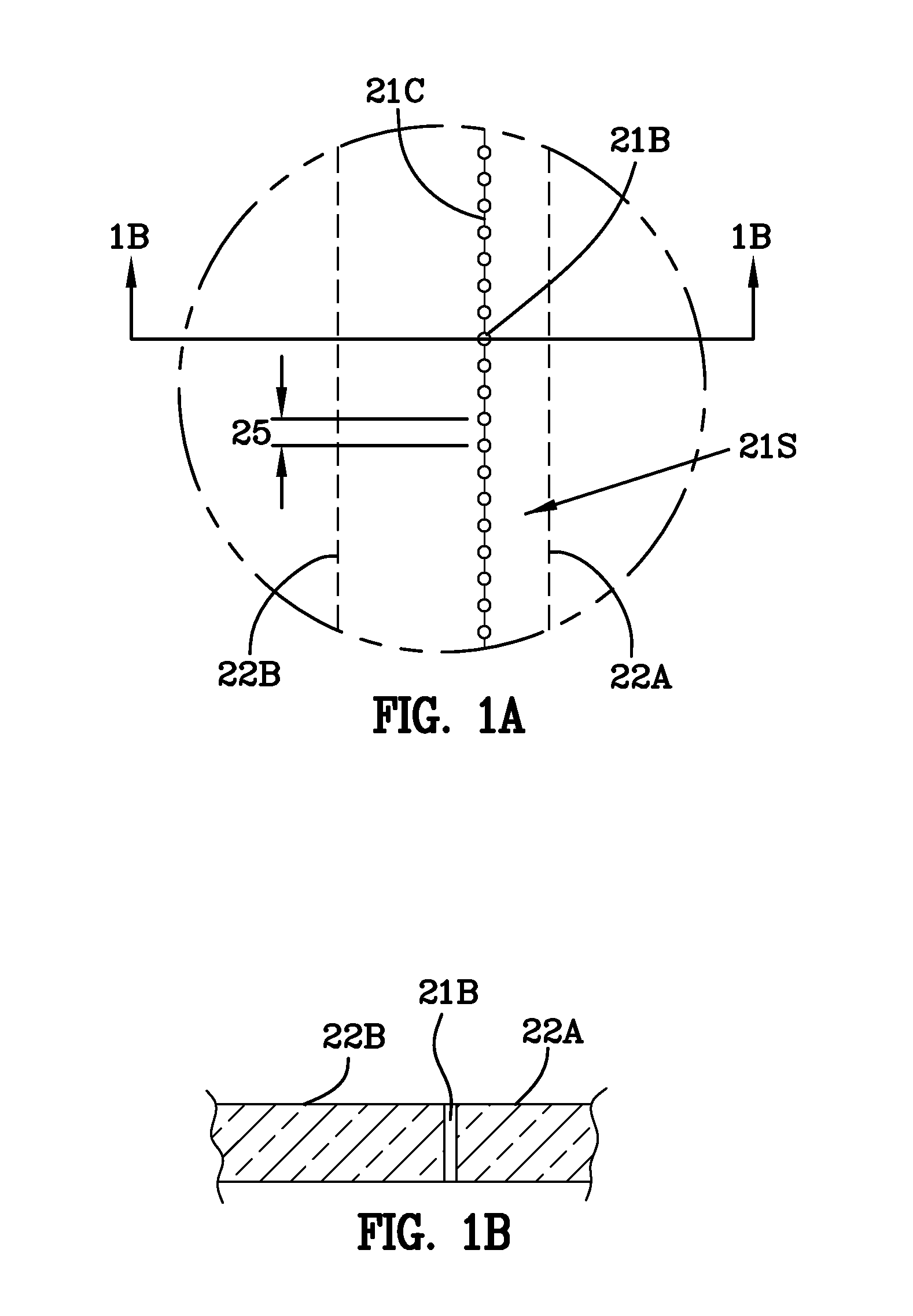
A method for machining and releasing closed forms from a transparent, brittle substrate includes using a burst of ultrafast laser pulses to drill patterns of orifices in the substrate. Orifices are formed by photoacoustic compression and they extend completely or partially in the transparent substrate. A scribed line of spaced apart orifices in the transparent substrate comprise a closed form pattern in the substrate. A heat source is applied in a region about said scribed line of spaced apart orifices until the closed form pattern releases from the transparent substrate.

Description

[0001]This patent application claims priority to and the benefit of U.S. provisional patent application Ser. No. 61 / 906,303 filed Nov. 19, 2013. U.S. provisional patent application Ser. No. 61 / 906,303 filed Nov. 19, 2013 is incorporated herein in its entirety by reference hereto.BACKGROUND OF THE INVENTION[0002]The present invention relates to an improved method of releasing closed forms (interior shapes) that have been cut out of a brittle material substrate.[0003]Currently, there are several methods for releasing geometrical shapes cut from a larger substrate sheet. Most of these methods include using a broad cut, additional release cuts to free the desired part, applying a pressing force, and, bending the substrate or pressure rolling the substrate. The problem with many of these methods is that they either leave:[0004]a damaged or rough peripheral edge, especially when the geometric shape is a complex one; or,[0005]a weakened edge or form with a plethora of microcracks therein.[...

Claims


Application Information

Patent Timeline
IPC IPC(8): B23K26/04B23K26/36
CPCB23K26/367B23K26/046C03B33/0222C03B33/091C03B33/0955C03B33/04B23K26/364B23K26/082B23K26/38B23K26/402B23K2103/50B23K26/0622B23K26/40
Inventor HOSSEINI, S. ABBAS
Owner ROFIN SINAR TECH
Why Eureka
Try Eureka