Rail attachment system for junction areas

a rail attachment and junction area technology, applied in the direction of railway fastening, railway track construction, track superstructure, etc., can solve the problems of high elasticity and high retaining force of such track fastening assemblies

Active Publication Date: 2015-05-21
SCHWIHAG
View PDF18 Cites 6 Cited by
  • Summary
  • Abstract
  • Description
  • Claims
  • Application Information

AI Technical Summary

Benefits of technology

[0027]Secure anchoring of the track-fastening assembly according to the invention, in particular in concrete substrates or steel constructions, may be assured by using special anchor bolt systems or screw connections.
[0028]Height compensation across the width of the track-fastening assembly according to the invention may be attained for instance with particularly simple means using suitable height compensation plates, and possibly also height compensation plates with different thicknesses.

Problems solved by technology

Thus both high elasticity and high retaining forces are required for such track-fastening assemblies.
The track-fastening assemblies known to date from practice are not able to satisfy all of the above-described criteria with the result that the lifting action is sufficiently smoothed and longitudinal and transverse displacements may be reliably absorbed without damage by the substrate.

Method used


Image

  • Rail attachment system for junction areas
  • Rail attachment system for junction areas
  • Rail attachment system for junction areas

Examples


Embodiment Construction

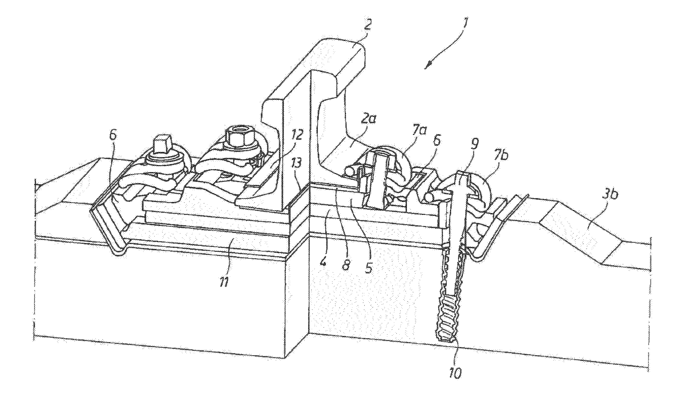
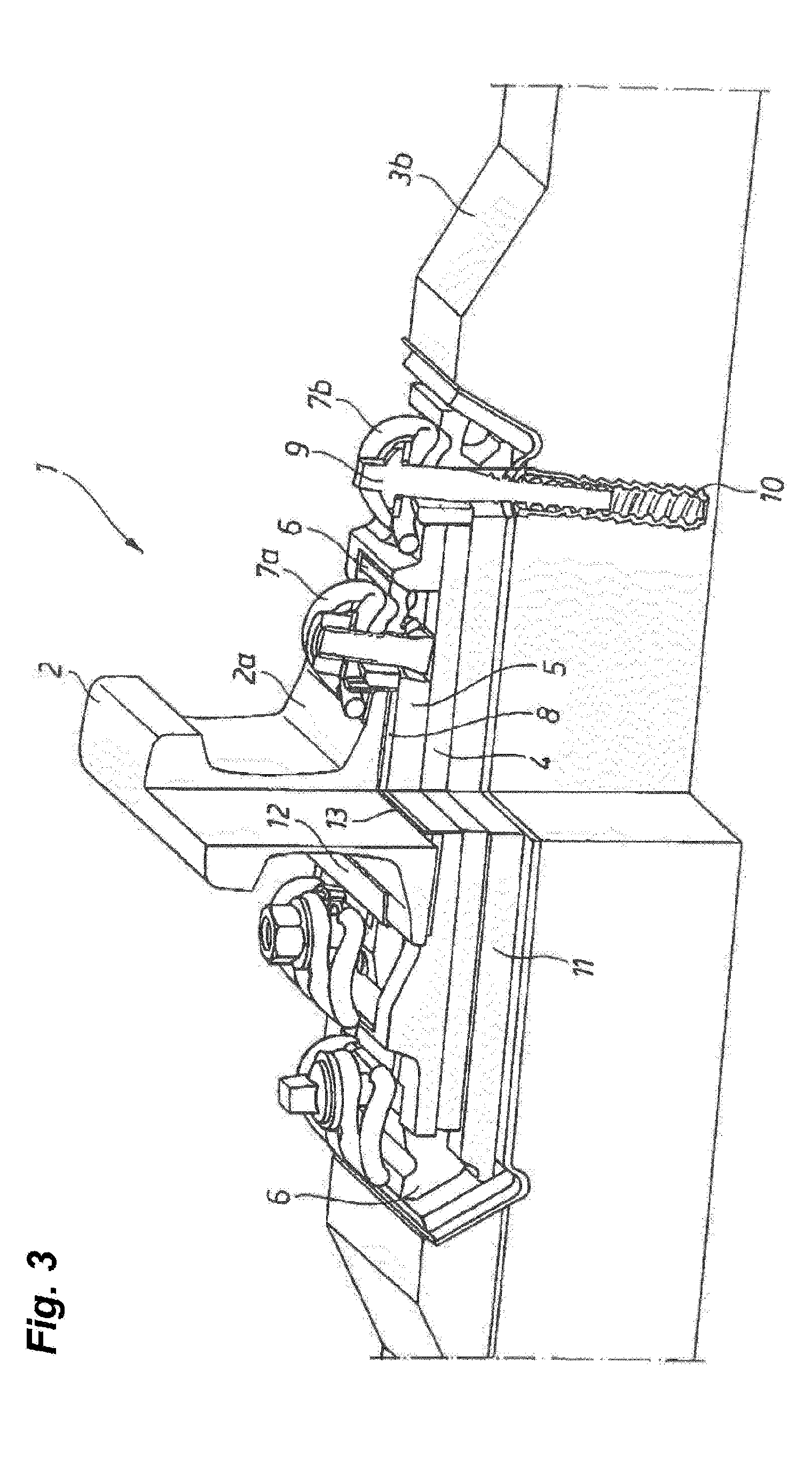
[0038]FIG. 3 shows a perspective and partly sectional view of a track-fastening assembly 1 via which a rail 2 may be attached to a concrete slab or sleeper 3b. The structure of the track-fastening assembly from bottom to top includes a height compensation plate 11 below a highly elastic intermediate plate 4. A height compensation plate is normally only necessary for later position correction after the start of construction or after lengthy use. Above the highly elastic intermediate plate 4 is a rail-attachment plate 5, for instance made of cast steel. Provided between the intermediate plate 5 and the bottom of a rail foot 2a is a lower slide plate 13, whose face turned toward the rail foot 2a is provided with a slide layer. In addition, an elastic intermediate layer 8 is provided below the lower slide plate 13 and above the rail-attachment plate 5. An upper slide plate 12 is supported on the upper face of the rail foot 2a and also has a slide layer on its face turned toward the rail...


PUM


Abstract

The invention relates to a rail attachment system (1) for attaching a rail (2) to a concrete support slab (3a) or a concrete sleeper (3b) or to a steel structure comprising an intermediate plate (4), a rail attachment plate (5) with angle guide plates (6, 6b) arranged thereon, at least two first tensioning clamps (7a) for clamping the rail foot (2a) to the rail attachment plate (5) as well as screws (9) and/or ankle bolts (10) and at least two second tensioning clamps for screwing the rail attachment system (1) to the underlying surface, characterized in that an elastic intermediate layer (8) is arranged between the rail (2) and the rail attachment plate (5), and the intermediate plate (4) is composed of a highly elastic material and/or comprises a steel plate (4), at least two second tensioning clamps (7b) for clamping the rail attachment plate (5) to the substructure, preferably via the intermediate plate (4), wherein the first and second tensioning clamps (7a, 7b) are embodied in a highly elastic fashion with a high tensioning force, are provided, and at least one upper sliding plate (12) is arranged between the rail foot (2a) and a first tensioning clamp (7a), and at least one lower sliding plate (13) is arranged between the rail foot (2a) and the elastic intermediate layer (8) and is attached by means of a steel support (14) in the case of a steel substructure.

Description

1. FIELD OF THE INVENTION[0001]The invention relates to track fastening assemblies for attaching a rail to a substrate, including an intermediate plate provided on a track supporting layer / concrete slab (fixed rail track) or on a sleeper (track ballast), a track attachment plate carrying angle guides, at least two first spring clips for clamping the rail foot to the rail-attachment plate, and screws and / or anchor bolts for screwing the track-fastening assembly to the track supporting layer or track ballast.[0002]The invention relates in particular to track-fastening assemblies as provided in so-called transition areas between different track beds having different elasticities. Such transition areas are located for instance at the entry to and exit from tunnels, at the ends of bridges, and the like, wherever the type and thus the elasticity of the substrate or subgrade changes and thus when loaded there are height movements in the gravel track ballast, i.e. in the track with the rail...

Claims


Application Information

Patent Timeline
Patent Type & Authority Applications(United States)
IPC IPC(8): E01B9/34E01B9/60
CPCE01B9/60E01B9/34E01B2/003E01B9/483E01B9/68E01B2201/08E01B2201/04E01B2/00E01B9/38E01B9/48
Inventor WALTER, DANIELLIENHARD, STEFANDANNEBERG, ERIKBUDA, ROLAND
Owner SCHWIHAG
Why Eureka
Try Eureka