
Component analyzing apparatus

a technology of components and analyzers, applied in the direction of optical radiation measurement, instruments, spectrometry/spectrophotometry/monochromators, etc., can solve the problems of troublesome operation, difficult to accurately measure the size of the measuring object, and the apparatus is large, so as to achieve high-accuracy component analysis

Inactive Publication Date: 2015-05-21
SEIKO EPSON CORP
View PDF11 Cites 13 Cited by
  • Summary
  • Abstract
  • Description
  • Claims
  • Application Information

AI Technical Summary

Benefits of technology

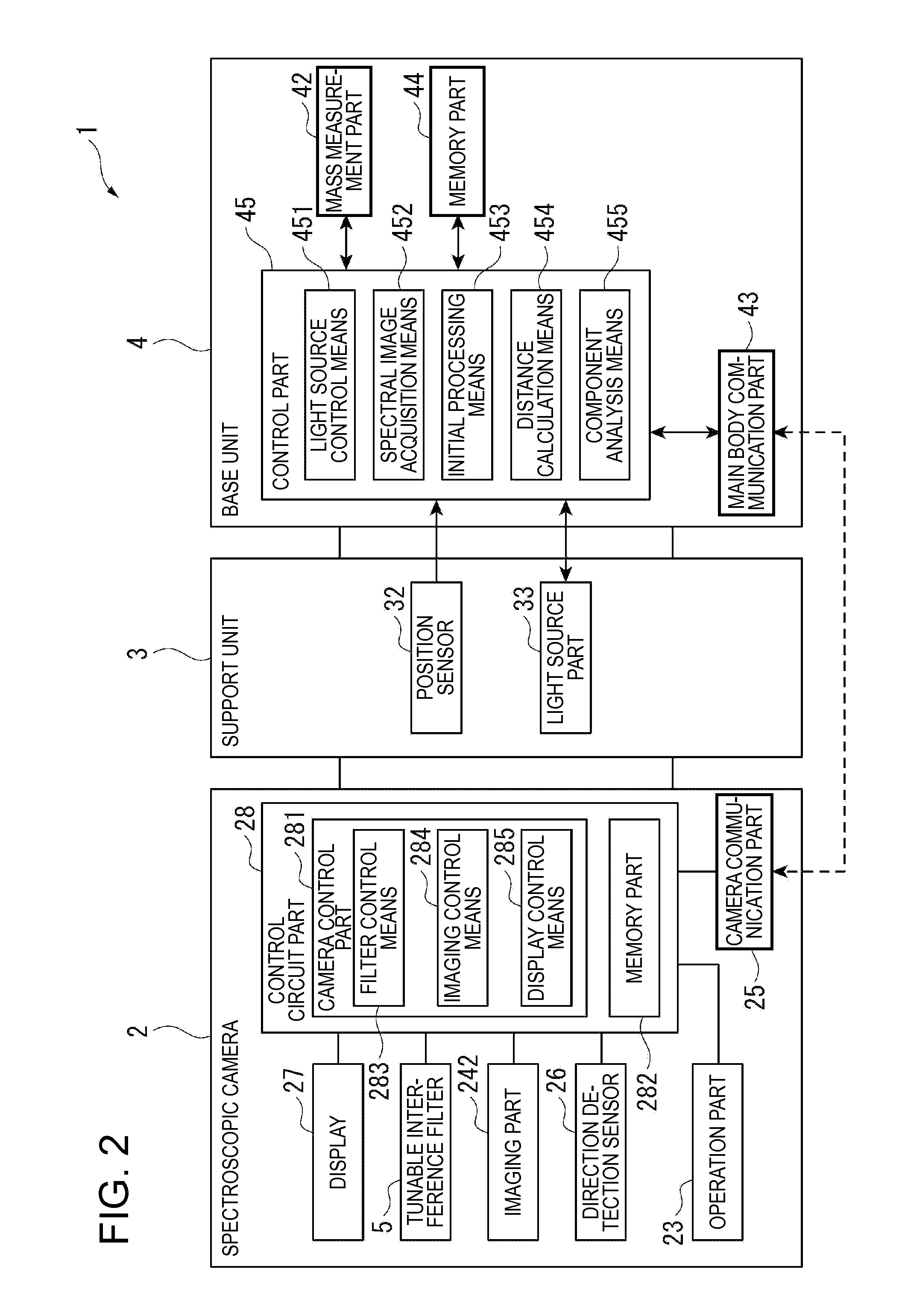
The invention provides a small component analyzing apparatus with high-accuracy component analysis capabilities. The apparatus includes a mass measurement part and a support unit that holds a spectroscopic imaging unit in place, resulting in reduced blurring of spectral images due to camera shake. The position of the support unit is detected, and the distance between the spectroscopic imaging unit and the mounting part is calculated, allowing for accurate measurement of the size of the object being analyzed. The apparatus also uses a tunable Fabry-Perot etalon for selecting light of a predetermined wavelength, resulting in a smaller and more compact spectroscopic imaging unit and component analyzing apparatus compared to other configurations.

Problems solved by technology

In the above described calorie measuring apparatus in Patent Document 1, it is necessary to house the measuring object in the chamber that prevents intrusion of outside light and electromagnetic wave, and there is a problem of upsizing of the apparatus.
Accordingly, the distance from the digital camera to the portable scale changes at each time of imaging, and there is a problem that it is difficult to accurately measure the size of the measuring object.
However, it is necessary to set the size indicator at each time of measurement and there is a problem that the operation is troublesome.
Further, in the portable calorie measuring apparatus, carrying the size indicator at every time is troublesome, and there is a problem that the measurement accuracy is lower when the size indictor is not carried.
When the spectral image is taken by the spectroscopic imaging unit, if a part in which the light from the light source part is regularly reflected exists, it may be impossible to acquire the correct optical spectrum in the part and perform a component analysis with high accuracy.

Method used


Image

  • Component analyzing apparatus
  • Component analyzing apparatus
  • Component analyzing apparatus

Examples


first embodiment

Advantages of First Embodiment

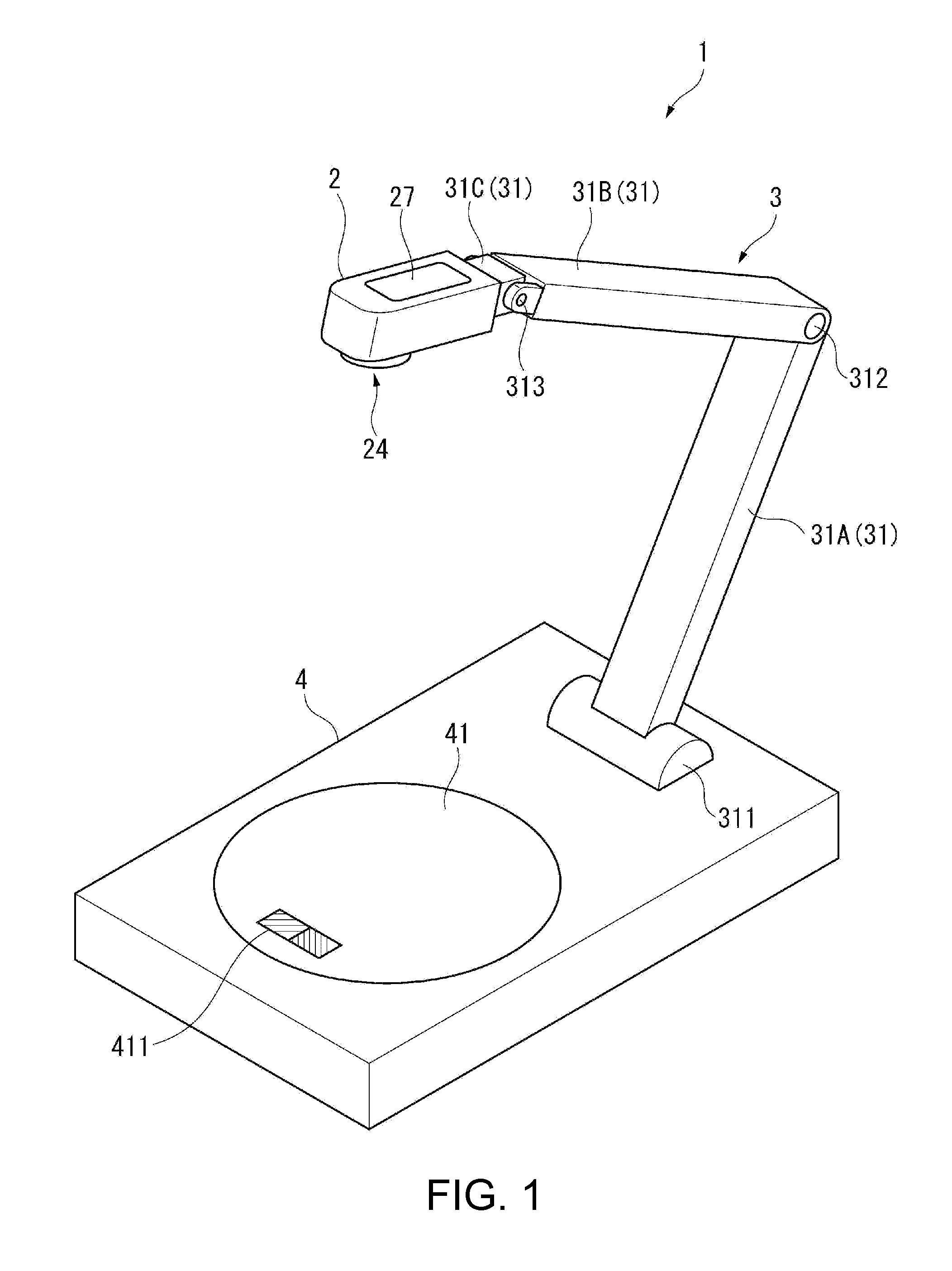
[0159]In the embodiment, the mass measurement part 42 is provided in the base unit 4, and thereby, the correct mass of the measuring object may be measured.

[0160]Further, the spectroscopic camera 2 is supported by the support unit 3 provided on the base unit 4, and thereby, there is no blur of the spectral image due to camera shake or the like, the distance from the spectroscopic camera 2 to the mounting part 41 of the base unit 4 is maintained constant, and the spectral image of the measuring object may be acquired at the distance. Therefore, the correct size of the measuring object may be calculated from the distance from the spectroscopic camera 2 to the mounting part 41, and the component contents of the measuring object may be calculated with high accuracy based on the mass of the measuring object and the amounts of light of the respective pixels of the spectral image.

[0161]Furthermore, the component analysis may be performed by the simple configur...

second embodiment

Advantages of Second Embodiment

[0191]In the embodiment, the light source part 33 is provided in the second arm 31B of the support unit 3 like the first embodiment.

[0192]Therefore, even when the abnormal pixel corresponding to the regular reflection part in which the light from the light source part 33 is regularly reflected exists in the first spectral image, the location of the regular reflection part of the measuring object may be changed by changing the position of the support unit 3. Therefore, the second spectral image after position change is acquired and the abnormal pixel in the first spectral image is replaced by the amount of light of the pixel of the second spectral image corresponding to the abnormal pixel, and thereby, the component analysis with high accuracy may be performed on the regular reflection part.

third embodiment

[0193]Next, the third embodiment according to the invention will be explained with reference to the drawings.

[0194]FIG. 11 is a perspective view showing a schematic configuration of a component analyzing apparatus of the embodiment.

[0195]As shown in FIG. 11, in a component analyzing apparatus 1A in the embodiment, a housing part 46 that houses a support unit 3A and the spectroscopic camera 2 is provided in the base unit 4.

[0196]The support unit 3A includes a first support 31D rotatably and axially supported inside of the housing part 46, a second support 31E extending and retracting with respect to the first support 31D, and the camera attachment part 31C rotatably and axially supported with respect to the second support 31E.

[0197]FIG. 12 schematically shows the support unit of the embodiment.

[0198]As shown in FIG. 12, the first support 31D is formed to have a hollow shape and is movable along the axial direction of the first support 31D when the second support 31E is inserted into ...


PUM


Abstract

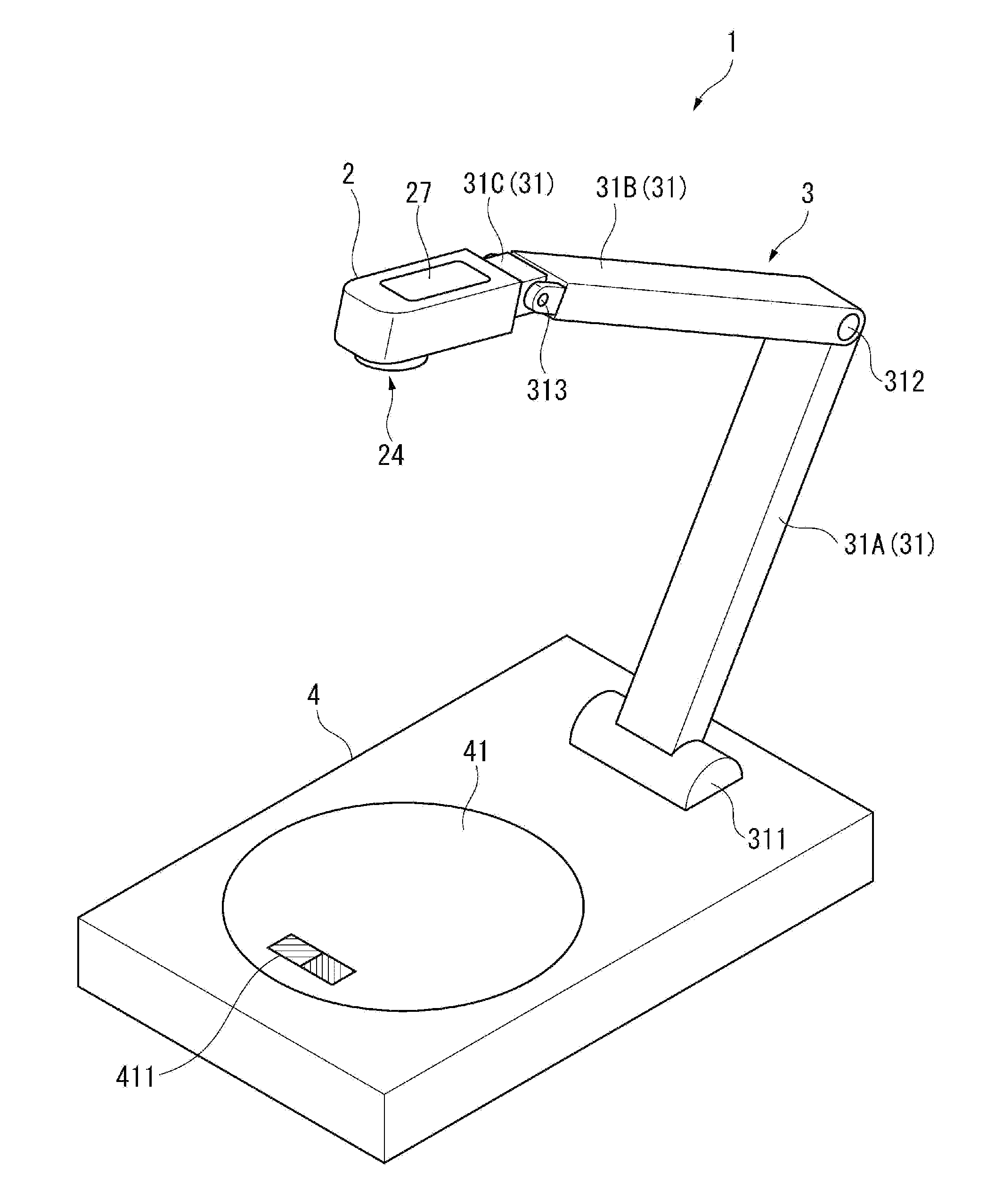
A component analyzing apparatus includes a base unit having a mounting part on which a measuring object is mounted and a mass measurement part that measures a mass of the measuring object, a spectroscopic camera that acquires a spectral image of the measuring object, a support unit provided on the base unit and supporting the spectroscopic camera in a location such that an imaging direction in the spectroscopic camera is a direction toward the mounting part and a distance between the mounting part and the spectroscopic camera is a predetermined distance, and a control part that analyzes components of the measuring object based on the spectral image and the mass measured by the mass measurement part.

Description

BACKGROUND[0001]1. Technical Field[0002]The present invention relates to a component analyzing apparatus etc.[0003]2. Related Art[0004]Recently, calorie measuring apparatuses for measuring calories of measuring objects have been known (for example, see Patent Document 1 (JP-A-2009-098015)).[0005]An apparatus disclosed in Patent Document 1 measures calories of a food as a measuring object mounted on a table provided in a chamber using calorie measuring means. In the apparatus, the chamber has an infrared light blocking film that blocks near-infrared light and an electromagnetic wave blocking member that blocks electromagnetic wave, and external infrared light and electromagnetic wave are blocked. Further, the apparatus includes a mass measuring device for measuring the mass of the measuring object mounted on the table. The calorie measuring means applies light in a near-infrared range to the measuring object within the chamber and receives the reflection light or transmission light w...

Claims


Application Information

Patent Timeline
IPC IPC(8): G01N21/25G01N33/02G01G19/00G01J3/28
CPCG01N21/255G01J3/2823G01N2201/06113G01G19/00G01N2201/062G01N33/02A23V2002/00G01J3/0291G01J3/26G01N21/01G01N21/278C12Q1/6872
Inventor SAKURAI, KAZUNORI
Owner SEIKO EPSON CORP
Learn More