Control device for vehicle drive device

Active Publication Date: 2015-05-21
AISIN AW CO LTD
View PDF3 Cites 0 Cited by
  • Summary
  • Abstract
  • Description
  • Claims
  • Application Information

AI Technical Summary

Benefits of technology

The technical effect of the patent text describes a configuration that allows for accurate and efficient control of the wheel transfer torque transferred from a speed change mechanism to the wheels of a vehicle. This is achieved through the use of target actuators and disengagement engagement elements that are all designed to operate within specific ranges. By setting determination values and operation indication values for each target actuator in relation to the transfer torque of each disengagement engagement element, the system can accurately determine whether or not the wheel transfer torque falls within the allowed range for each target actuator. This ensures that the vehicle travel state is stable and reduces any discomfort or uncomfortable feelings for the driver. Furthermore, the configuration improves the conversion accuracy of the element transfer torque value and helps in limiting the shift speed when the disengagement engagement element is engaged, which further enhances the accuracy of the determination and operation indication values.

Problems solved by technology

However, it is assumed that during travel in the neutral state, the operating state of an actuator for the engagement element which has been controlled so as to be disengaged may be unintentionally varied because of erroneous operation of a control device or a failure of the actuator.
In such a case, negative torque (braking torque) may be transferred from the speed change mechanism to the wheels during travel in the neutral state to affect the travel state of the vehicle or give an uncomfortable feeling to a driver.
However, the device according to Patent Document 2 detects a locked state of the speed change mechanism, and may not determine wheel transfer torque transferred because of unintentionally produced transfer torque of the disengagement engagement element during traveling in the neutral state.
In addition, the device according to Patent Document 2 makes a determination on the basis of the sum of current values for the plurality of actuators, and therefore may not accurately determine the effect of the current values for the actuators on the wheel transfer torque.

Method used


Image

  • Control device for vehicle drive device
  • Control device for vehicle drive device
  • Control device for vehicle drive device

Examples


Embodiment Construction

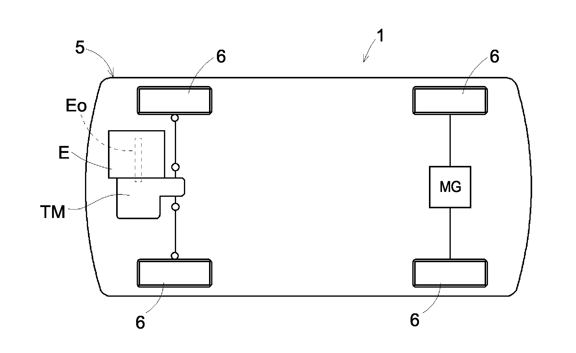
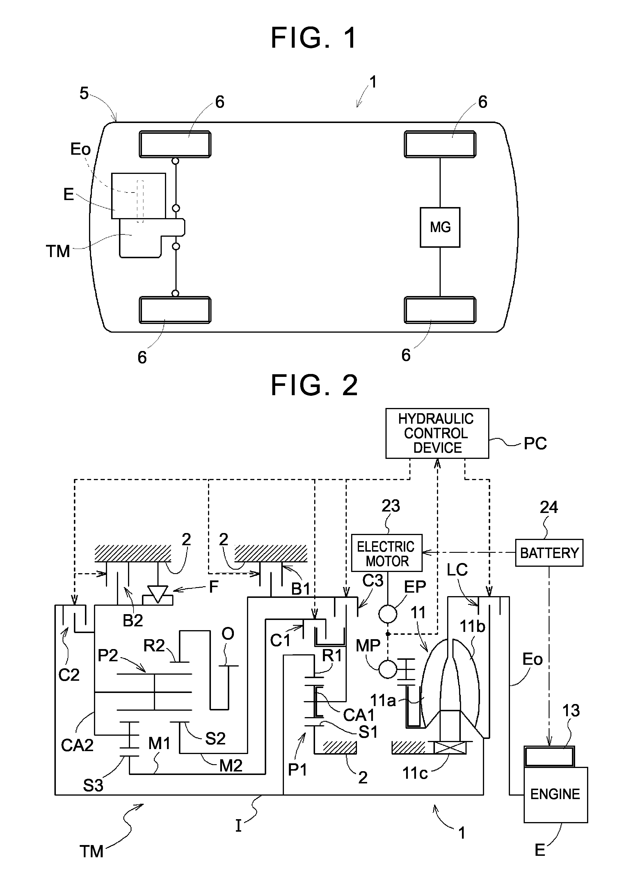
[0042]A control device 30 for a vehicle drive device that controls a vehicle drive device 1 according to an embodiment of the present invention will be described with reference to the drawings. FIGS. 1 and 2 are each a schematic diagram illustrating a schematic configuration of the vehicle drive device 1 and the control device 30 according to the embodiment.

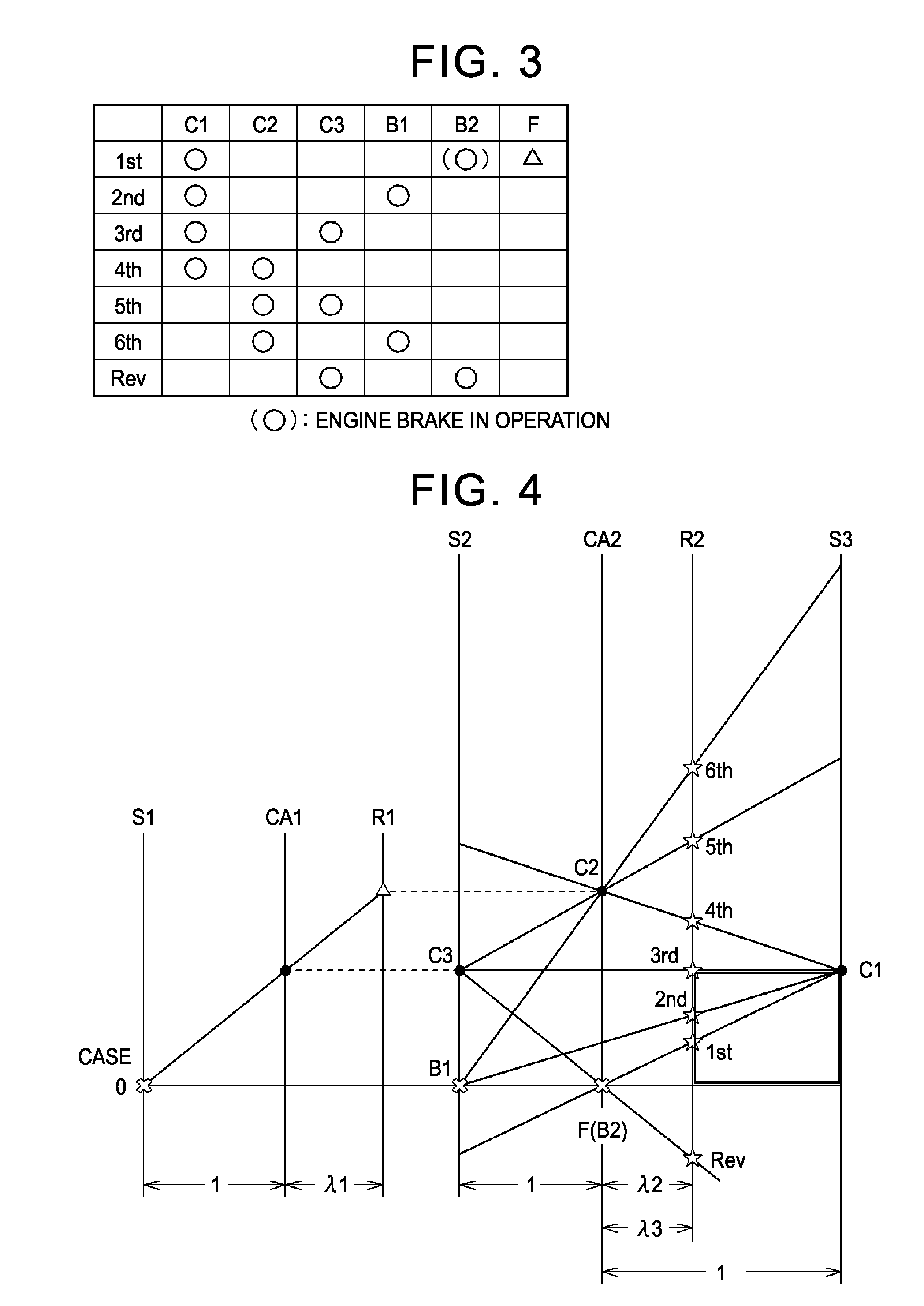
[0043]In the embodiment, as illustrated in FIG. 2, the vehicle drive device 1 includes an input shaft I drivably coupled to an engine E serving as a drive force source for wheels 6, an output gear O drivably coupled to the wheels 6, a speed change mechanism TM that includes a plurality of engagement elements C1, B1, . . . to establish a plurality of shift speeds in accordance with the engagement / disengagement state of the plurality of engagement elements C1, B1, . . . and that transfers rotation of the input shaft I to the output gear O while changing the speed of the rotation with the speed ratio of each shift speed, and a rotar...


PUM


Abstract

A control device for a vehicle drive device includes performing neutral travel control in which disengagement / engagement elements are disengaged with the wheels rotating so the state of a speed change mechanism is controlled into a neutral state where transfer of a drive force between the input member to the engine and the output member to the wheels is not performed, and the wheels are driven by a rotary electric machine drive force; and comparing an operating state value of each of target actuators that control the state of the disengagement / engagement elements, and a determination value so torque from the speed change mechanism to the wheels because of torque transferred by each of the disengagement / engagement elements, falls within an allowable range during neutral travel control, and determines whether the torque transferred from the speed change mechanism to the wheels falls within the allowable range.

Description

TECHNICAL FIELD[0001]The present invention relates to a control device for a vehicle drive device that controls a vehicle drive device including an input member drivably coupled to an internal combustion engine serving as a drive force source for wheels, an output member drivably coupled to the wheels, a speed change mechanism that includes a plurality of engagement elements to establish a plurality of shift speeds in accordance with the engagement / disengagement state of the plurality of engagement elements and that transfers rotation of the input member to the output member while changing the speed of the rotation with the speed ratio of each shift speed, and a rotary electric machine drivably coupled to the wheels not via the speed change mechanism.BACKGROUND ART[0002]A device disclosed in Patent Document 1 mentioned below is known as an example of the vehicle drive device described above. In the device according to Patent Document 1, an engagement element provided in a speed chan...

Claims


Application Information

Patent Timeline
IPC IPC(8): B60W20/00B60W10/11F16H61/12
CPCB60W20/50F16H61/12Y10S903/945F16H2061/1288B60W10/11F16H2061/1208F16H2061/1276
Inventor SUZUKI, TAKEHIKOTAJIMA, YOICHITAGUCHI, MASATOSHIKUBOKAWA, MINORUKUSAMIZU, TOMOHIRO
Owner AISIN AW CO LTD
Why Eureka
Try Eureka